Magnetic suspension with integrated motor

a technology of integrated motors and magnetic suspensions, which is applied in the direction of magnets, magnetic holding devices, magnetic bodies, etc., can solve the problems of suspension loss, power failure or servo malfunction, and the presence of its own power and servo complexity

Inactive Publication Date: 2008-05-01
STORAASLI ALLEN GARY
View PDF14 Cites 8 Cited by
  • Summary
  • Abstract
  • Description
  • Claims
  • Application Information

AI Technical Summary

Benefits of technology

[0007]The present invention solves the above-mentioned problems by demonstrating a passive magnetic suspension that can be used to act as or alternatively power an electric motor, a generator, or other device. The magnetic suspension consists of at least one magnetic element (typically a disc) fixed to a stator element (typically a shaft) and surrounded by two or more planetary magnets on the rotor. Having all magnet poles oriented in the same direction results in strong repulsion forces which provide the radial magnetic suspension. (This arrangement is in contrast to prior art which has one central disc and one exterior magnetic ring.) The plurality of planetary rotor magnets (which can also be seen as segmenting the rotor magnetic ring) creates multiple unipolar magnetic fields, enabling the introduction of windings to output the generated torque and provide motor function. The integrated motor function eliminates the addition of a separate motor.

Problems solved by technology

In high speed energy storage flywheels and other gyro applications, magnetic suspensions eliminate friction, the need for lubrication, and overall life limitations.
Obviously, this type of arrangement presents its own disadvantages.
The active magnetic suspension, such as the one disclosed in U.S. Pat. No. 6,320,290 to Kanebako, requires additional power and servo complexity; and the suspension is lost with power failure or servo malfunction.
Ritts' device, however, is simply a display apparatus and does not provide motor function.

Method used


Image

  • Magnetic suspension with integrated motor
  • Magnetic suspension with integrated motor
  • Magnetic suspension with integrated motor

Examples


Embodiment Construction

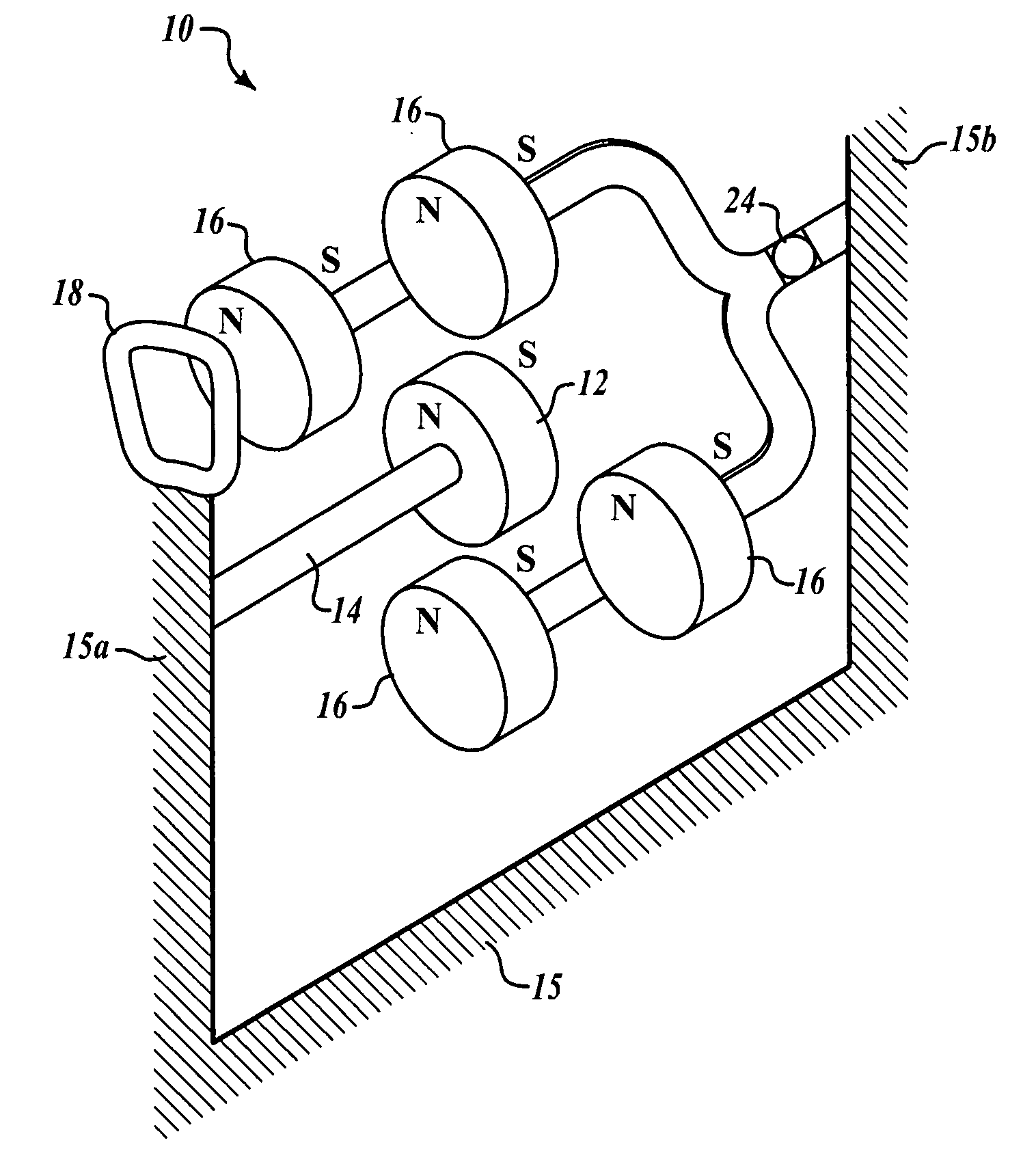
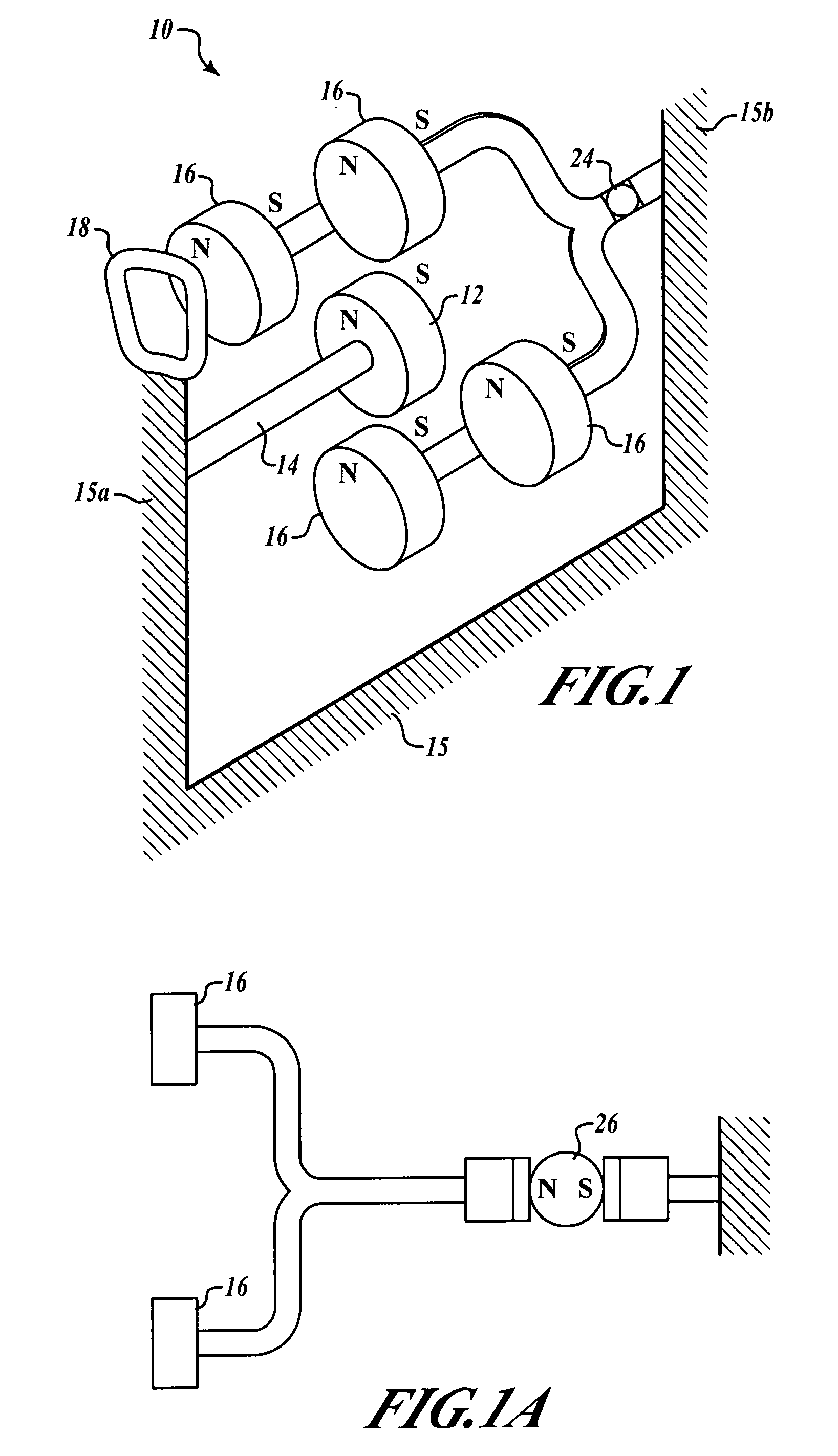
[0015]FIG. 1 shows how the magnetic suspension motor invention 10 may comprise at least one central stator magnetic element, here a disc, 12 fixed to a stator shaft 14 and surrounded by a plurality of planetary rotor magnets 16, generally coplanar therewith. At least two rotor magnets are recommended for stability; in this preferred embodiment, four have been used for the single stator magnet. Likewise, several stator magnets 12 could be used and spaced apart along an elongated stator shaft 14, each one having generally coplanar planetary rotor magnets. Each axially polarized dipole magnet (rotor or stator) has two poles designated as N or S (other designations could be used; however, N and S are typically used according to convention). Having all like magnet poles oriented in a common direction results in strong repulsion forces which provide the radial magnetic suspension. This arrangement is in contrast to prior art suspensions which comprise one central magnet disc surrounded by...


PUM

PropertyMeasurementUnit
diameteraaaaaaaaaa
resistanceaaaaaaaaaa
magneticaaaaaaaaaa

Abstract

A passive magnetic suspension acts as an electric motor with the introduction of lead means, such as motor windings, to harness and output the generated torque or voltage from the magnetic fields. The magnetic suspension consists of at least one magnetic element (typically a disc) fixed to a stator element (typically a shaft) and surrounded by two or more planetary magnets on the rotor. Having all magnet poles oriented in the same direction results in strong repulsion forces which provide the radial magnetic suspension. Segmenting the rotor magnet creates multiple unipolar magnetic fields, enabling additional possibilities in the introduction of windings to output the generated torque and provide motor function.

Description

RELATED APPLICATIONS[0001]This application is related to and claims priority under 35 U.S.C. 119(e) to U.S. provisional application Ser. No. 60 / 855,009, entitled “Magnetic Suspension with Integrated Motor,” filed on Oct. 27, 2006, with inventor Allen Gary Storaasli, which is hereby incorporated by reference in its entirety.FIELD OF THE INVENTION[0002]This invention pertains generally to suspension systems and more particularly to a rotary magnetic suspension system incorporating an integrated brushless DC motor that develops motor torque from fields between fixed coils and the orbiting magnet poles.BACKGROUND OF THE FIELD[0003]Magnetic suspensions have been used to several advantages over ball or journal bearings—such as elimination of wear and friction. In fluid pump applications, magnetic bearings provide a clear flow path. In cryogenic applications, magnetic bearings can eliminate low temperature lubrication problems and material CTE problems. It is therefore desirable to provide...

Claims


Application Information

Patent Timeline
Patent Type & Authority Applications(United States)
IPC IPC(8): H01F7/08
CPCF16C32/044H02N15/00H02K7/09H01F7/0236F16C32/0425
Inventor STORAASLI, ALLEN GARY
Owner STORAASLI ALLEN GARY
Why Eureka
Try Eureka