

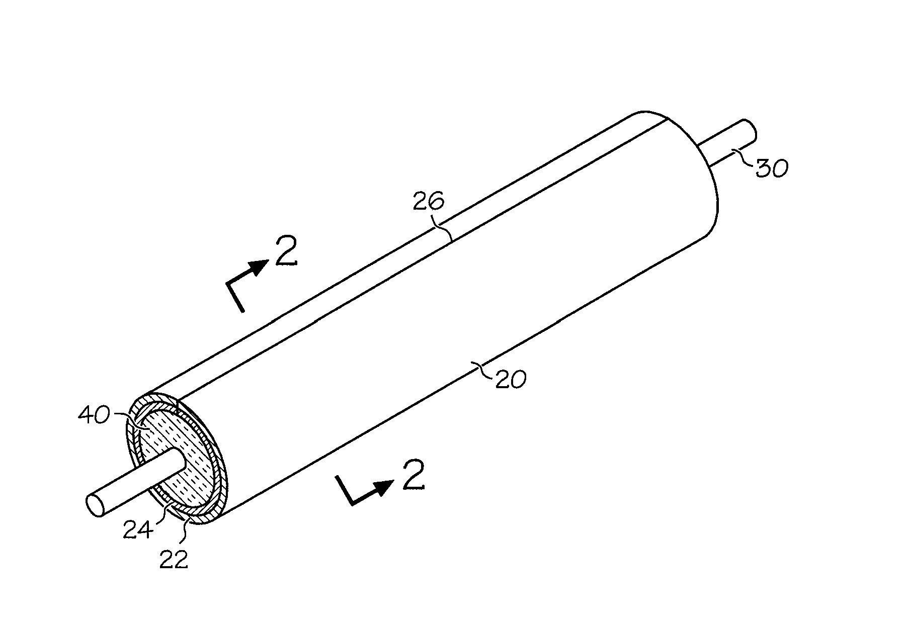
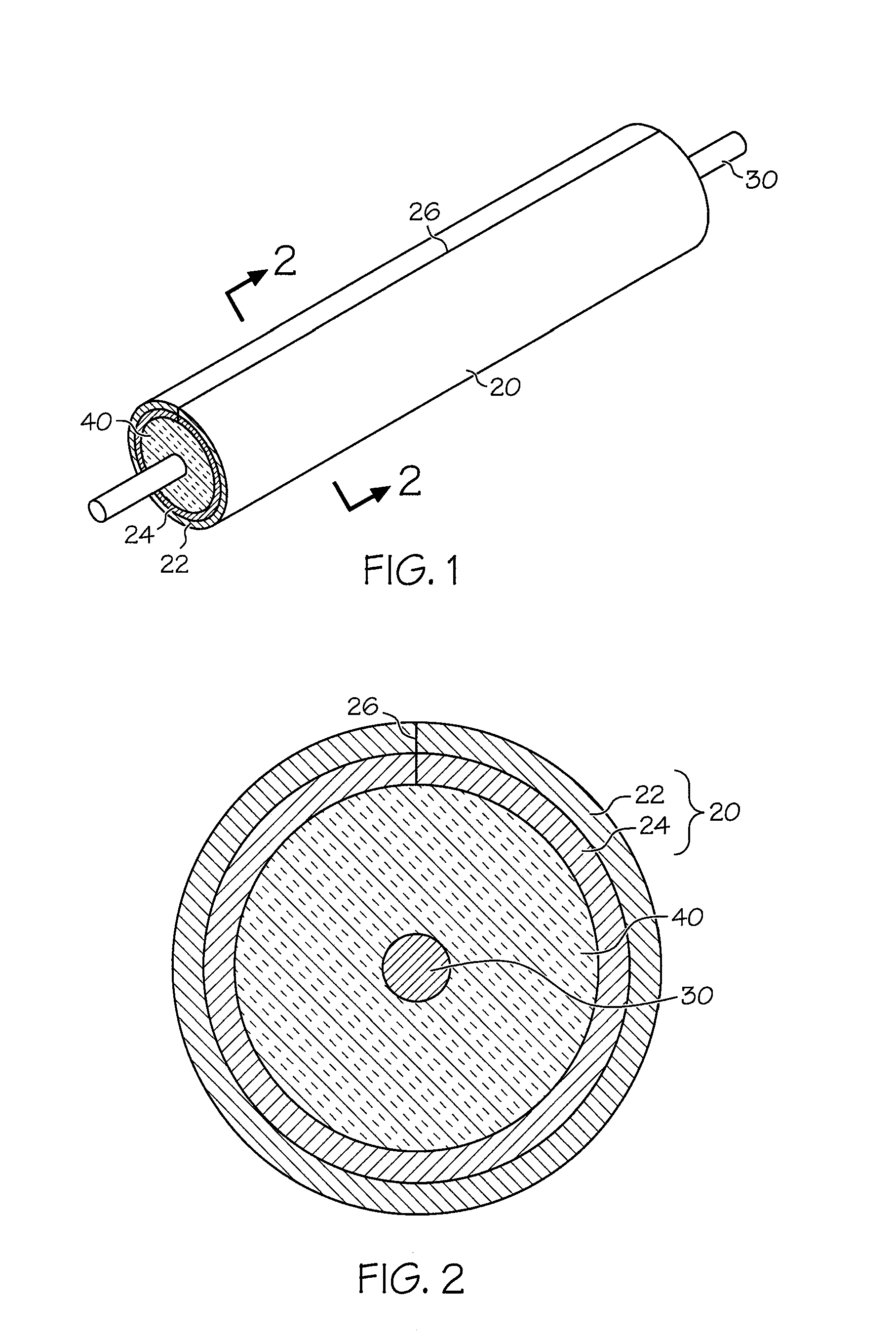
Heating element sheaths
a heating element and sheath technology, applied in the field of heating elements, can solve the problem of significantly higher cost of nickel-based alloys than other sheath materials
- Summary
- Abstract
- Description
- Claims
- Application Information
AI Technical Summary
Benefits of technology
Problems solved by technology
Method used
Image

Examples
example i
[0031]In this example, the layer ratio of INCOLOY alloy 840 to S30403 was 20 / 80 in the bonded material. The material for this example was fabricated using cold roll bonding. The raw materials prior to bonding, INCOLOY alloy 840 and S30403, were 0.012″ and 0.045″ thick respectively. The raw materials were cold roll bonded to a total clad thickness of 0.0170″, where the INCOLOY alloy 840 layer was 0.0034″ thick and the S30403 layer was 0.0136″ thick. The bonded material was then annealed at 1900° F. (˜1038° C.) to improve the bond strength and anneal both of the components of the bonded material. Following bonding, the material was slit to the required width to form seam welded tubes of a specified diameter. The mechanical properties of the material produced by this example are shown in Table 1 below.
TABLE 1Gauge0.0170″Tensile Strength91.2 ksiYield Strength36.6 ksiPercent Elongation53.3%Microhardness (INCOLOY alloy 840 layer)134 DPHMicrohardness (S30403 layer)150 DPHASTM Grain Size (I...
example ii
[0032]In this example, the layer ratio of INCOLOY alloy 840 to S30403 was 32 / 68 in the bonded material. The raw materials prior to bonding, INCOLOY alloy 840 and S30403, were 0.0136″ and 0.0290″ thick respectively. The raw materials were cold roll bonded to a total clad thickness of 0.0170″, where the INCOLOY alloy 840 layer was 0.0054″ thick and the S30403 layer was 0.0116″ thick. The bonded material was then annealed at 1900° F. (˜1038° C.) to improve the bond strength and anneal both of the components of the bonded material. Following bonding, the material was slit to the required width to form seam welded tubes of a specified diameter. The mechanical properties for the 32 / 68 ratio material measured:
TABLE 2Gauge0.0170″Tensile Strength86.6 ksiYield Strength35.0 ksiPercent Elongation53.1%Microhardness (INCOLOY alloy 840 layer)141 DPHMicrohardness (S30403 layer)149 DPHASTM Grain Size (INCOLOY alloy 840 layer)9.5ASTM Grain Size (S30403 layer)9.0
example iii
[0033]In this example, the layer ratio of INCOLOY alloy 840 to S30403 was 40 / 60 in the bonded material. The raw materials prior to bonding, INCOLOY alloy 840 and S30403, were 0.0170″ and 0.0255″ thick respectively. The raw materials were cold roll bonded to a total clad thickness of 0.0170″, where the INCOLOY alloy 840 layer was 0.0068″ thick and the S30403 layer was 0.0102″ thick. The bonded material was then annealed at 1900° F. (˜1038° C.) to improve the bond strength and anneal both of the components of the bonded material. Following bonding, the material was slit to the required width to form seam welded tubes of a specified diameter. The mechanical properties for the 40 / 60 ratio material measured:
TABLE 3Gauge0.0170″Tensile Strength92.4 ksiYield Strength37.4 ksiPercent Elongation49.5%Microhardness (INCOLOY alloy 840 layer)126 DPHMicrohardness (S30403 layer)148 DPHASTM Grain Size (INCOLOY alloy 840 layer)8.5ASTM Grain Size (S30403 layer)9.5
[0034]The difference of this invention ...
PUM
| Property | Measurement | Unit |
|---|---|---|
| Fraction | aaaaa | aaaaa |
| Fraction | aaaaa | aaaaa |
| Fraction | aaaaa | aaaaa |
Abstract
Description
Claims
Application Information