
Fuel cell

a fuel cell and cell technology, applied in the field of fuel cells, can solve the problems of increasing the over all size of the fuel cell, increasing the complexity and fabrication cost, and introducing severe assembly challenges for the bonding of membrane electrolyte with pure adhesives, and achieving the effect of enabling design flexibility and complexity reducing the cost of pure adhesives, and increasing the durability of the fuel cell assembly

Inactive Publication Date: 2008-05-01
THE BOARD OF TRUSTEES OF THE LELAND STANFORD JUNIOR UNIV +1
View PDF2 Cites 3 Cited by
  • Summary
  • Abstract
  • Description
  • Claims
  • Application Information

AI Technical Summary

Benefits of technology

The invention is a fuel cell that is simple and efficient to make and operate. It uses a photo-sensitive material and printed circuit board fabrication techniques to create boundary structures for fluid conductance, as well as micro-channel structures to reduce dead zones. The cell also uses adhesive bonding instead of mechanical clamping elements for efficient operation. The invention provides a fuel cell assembly with improved fuel conductance, reduced dead zones, and increased efficiency.

Problems solved by technology

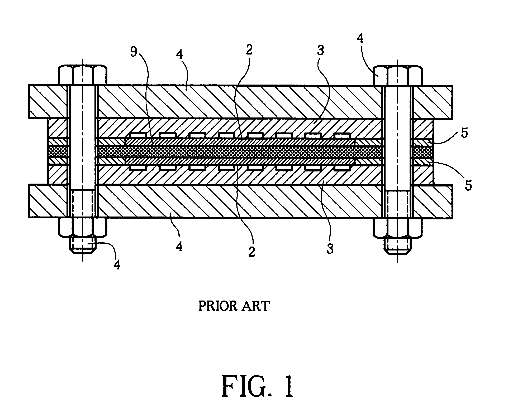
Consequently, the mechanical structure involved for providing the required compressive force and for evenly distributing that compressive force across the fuel cell's core structure increases the fuel cell's over all size, complexity and fabrication cost.
However, bonding of a membrane electrolyte with pure adhesives introduces severe assembly challenges due to compatibility issues between the membrane electrolyte and the pure adhesive.
Furthermore, pure adhesives are known to fail readily when subject to expansion of the membrane electrolyte as well as varying degrees of moisture content.

Method used


Image

  • Fuel cell
  • Fuel cell
  • Fuel cell

Examples


Embodiment Construction

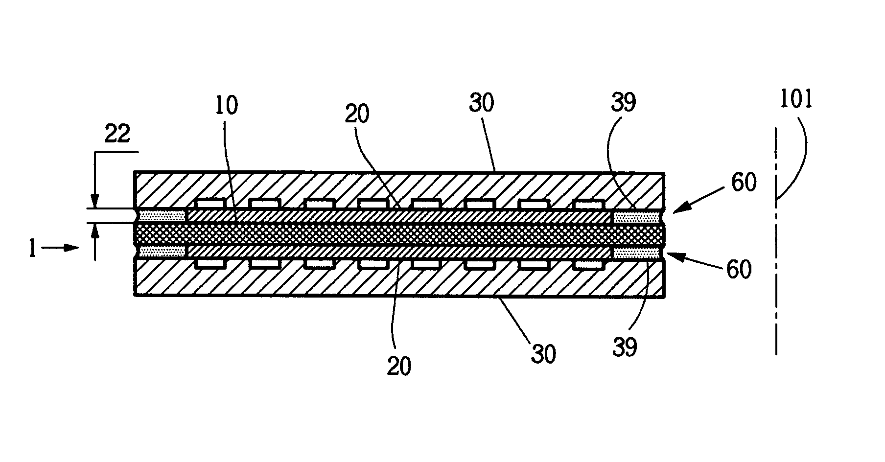
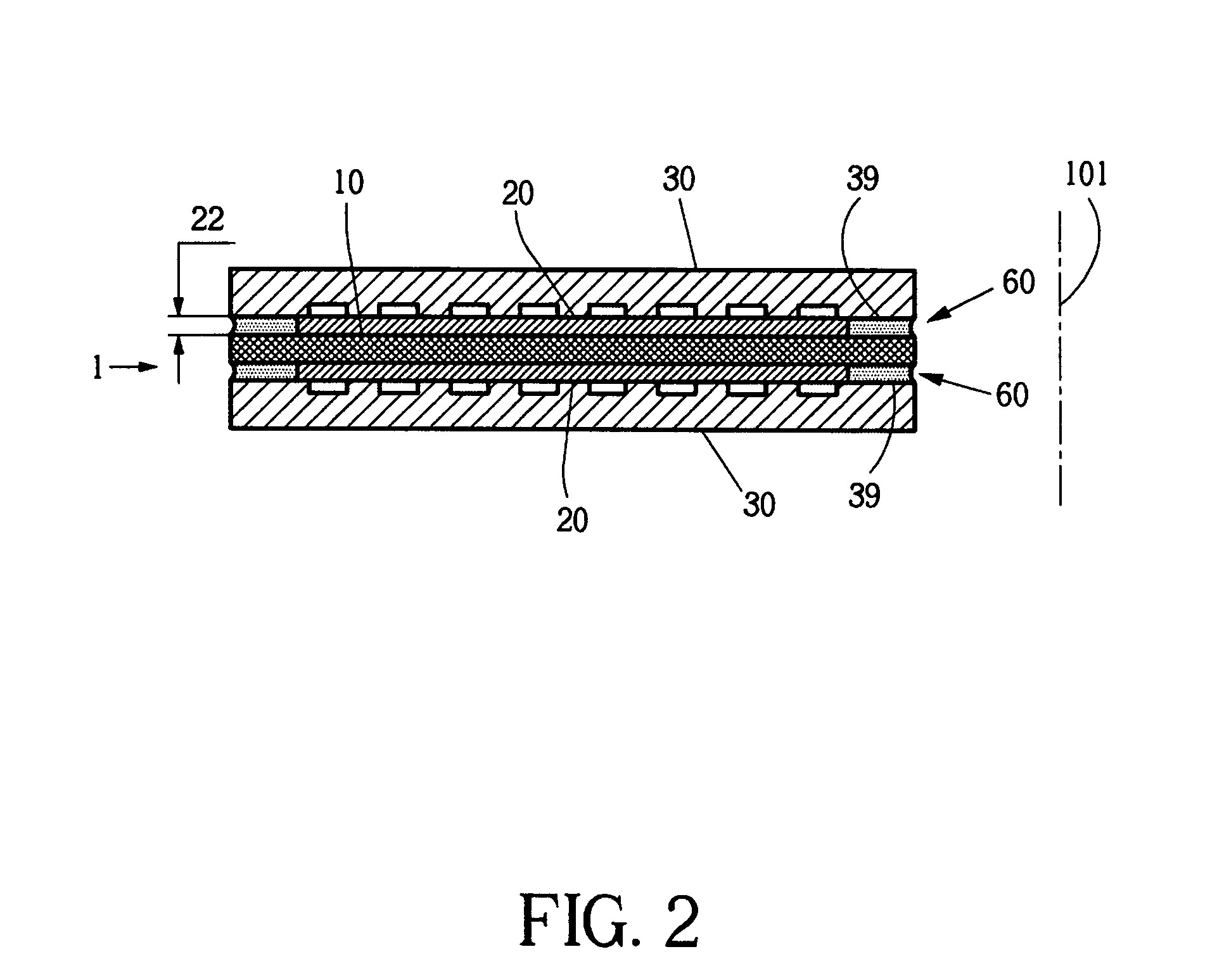
[0066] In the present invention novel design configurations and fabrication methods for compact fuel cells with high power density are described. Referring to FIG. 2, a basic fuel cell device 1 in accordance with the present invention includes an ion-conducting electrolyte membrane 10 between two electrodes 20, backed by backing layers or backing structures 30. The backing structures feature flow distribution channels 31, 32, 35, 36, 37, 38 (see FIGS. 3-11) for fluid supply and fluid exhaust. A catalyst on one electrode promotes separation of ions and electrons at the fuel side. Only the ions conduct through the electrolyte, and recombine with electrons at the oxidant side. The electrons are conducted through an external circuit, thus supplying electrical power. The layers of the fuel cell 1 are assembled along the assembly axis 101.

[0067] For ease of the invention the numerous aspects of the invention are initially described in separate chapters. Cross dependency of the individual...


PUM

PropertyMeasurementUnit
heightaaaaaaaaaa
heightaaaaaaaaaa
heightaaaaaaaaaa

Abstract

A simple, inexpensive and highly efficient fuel cell has boundary structures made of a photo-sensitive material in combination with selective patterning. Printed circuit board (PCB) fabrication techniques combine boundary structures with two and three dimensional electrical flow path. Photo-sensitive material and PCB fabrication techniques are alternately or combined utilized for making micro-channel structures or micro stitch structures for substantially reducing dead zones of the diffusion layer while keeping fluid flow resistance to a minimum. The fuel cell assembly is free of mechanical clamping elements. Adhesives that may be conductively contaminated and / or fiber-reinforced provide mechanical and eventual electrical connections, and sealing within the assembly. Mechanically supporting backing layers are pre-fabricated with a natural bend defined in combination with the backing layers' elasticity to eliminate massive support plates and assist the adhesive bonding. Proton insulation between adjacent and electrically linked in-plane cell elements is provided by structural insulation within the central membrane.

Description

CROSS-REFERENCE TO RELATED APPLICATIONS [0001] This application is a divisional of U.S. patent application Ser. No. 10 / 435,610, filed May 9, 2003, which is incorporated herein by reference. U.S. patent application Ser. No. 10 / 435,610, filed May 9, 2003 claims the benefit of U.S. Patent Application No. 60 / 379,524 filed May 9, 2002, U.S. Patent Application 60 / 408,732 filed Sep. 6, 2002, and U.S. Patent Application 60 / 458,116 filed Mar. 26, 2003, all of which are hereby incorporated by reference. FIELD OF INVENTION [0002] The invention relates generally to fuel cells, and more specifically to fuel cells preferably constructed from photo-patterned laminates, preferably bonded with fiber-reinforced adhesive and having massively parallel distribution channels. BACKGROUND OF INVENTION [0003] A fuel cell is an electromechanical device that produces electrical current from chemical reactions. The essential form of a fuel cell includes an ion-conducting electrolyte between two electrodes that...

Claims


Application Information

Patent Timeline
Patent Type & Authority Applications(United States)
IPC IPC(8): H01M8/02H01M4/86H01M4/88H01M8/00H01M8/10H01M8/24
CPCH01M8/0221H01M8/0226H01M8/0228H01M8/0232H01M8/0256Y02E60/50H01M8/0269H01M8/0271H01M8/241H01M8/2415H01M8/247H01M8/0263H01M8/2484H01M8/02H01M8/24H01M8/2483
Inventor SASAHARA, JUNBRAITHWAITE, DANIELCHA, SUK-WONFABIAN, TIBORKUBOTA, TADAHIROKURIYAMA, NARIAKILEE, SANG-JOON JOHNO'HAYRE, RYANPRINZ, FRIEDRICH B.SAITO, YUJISUZUKI, TOSHIFUMI
Owner THE BOARD OF TRUSTEES OF THE LELAND STANFORD JUNIOR UNIV
Learn More