Full traction differential with hybrid gearing

a hybrid gearing and full traction technology, applied in the direction of gearing details, gearing, mechanical equipment, etc., can solve the problems of improper alignment of improperly positioned balance gears, and achieve the effect of improving the tooth contact pattern, increasing the effectiveness of torque transfer, and increasing the traction

Inactive Publication Date: 2008-05-01
TORVEC INC
View PDF28 Cites 21 Cited by
  • Summary
  • Abstract
  • Description
  • Claims
  • Application Information

AI Technical Summary

Benefits of technology

[0015]The compact, all-gear full-traction differential includes meshing pairs of side-gear worms and worm-wheel balance gears having a “hybrid” design that results in an improved tooth contact pattern between the side gears and the central portion of the balance gears and more closely approximates true worm / worm-wheel characteristics, inherently increasing the effectiveness of torque transfer to the wheel with greater traction, increasing shock resistance, and permitting a timing relationship between all the gears of the differential that remarkably simplifies assembly. Preferably, the teeth of each side-gear worm have an involute profile but are cut with only plunge feed, while the teeth of the worm-wheel portions of the balance gears are helicoid worms having tip and root modifications made by a convex-shaped cutter. The side-gear worm teeth have a helix angle equal to or greater than 45° and significantly chamfered ends, and the gears are designed to provide a gear ratio between 1.5:1 and 2.5:1. The numbers of teeth in the (a) spur-gear portion and (b) worm-wheel portion of each balance gear, and (c) in each side-gear worm are all divisible by 2 or by 3, preferably by both 2 and 3. Further, any improperly positioned balance gear does not align properly with its respective mounting hole in the housing and, by merely rotating such a misaligned balance gear by one tooth in either direction, correct alignment and gear timing is achieved.

Problems solved by technology

Further, any improperly positioned balance gear does not align properly with its respective mounting hole in the housing and, by merely rotating such a misaligned balance gear by one tooth in either direction, correct alignment and gear timing is achieved.

Method used


Image

  • Full traction differential with hybrid gearing
  • Full traction differential with hybrid gearing
  • Full traction differential with hybrid gearing

Examples


Embodiment Construction

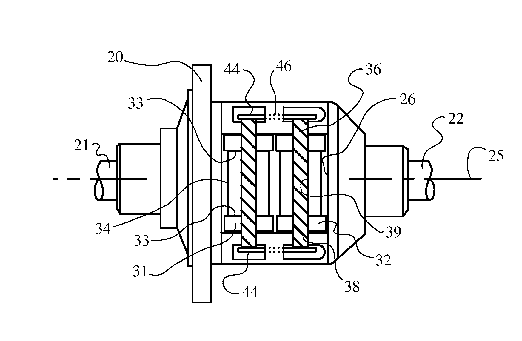
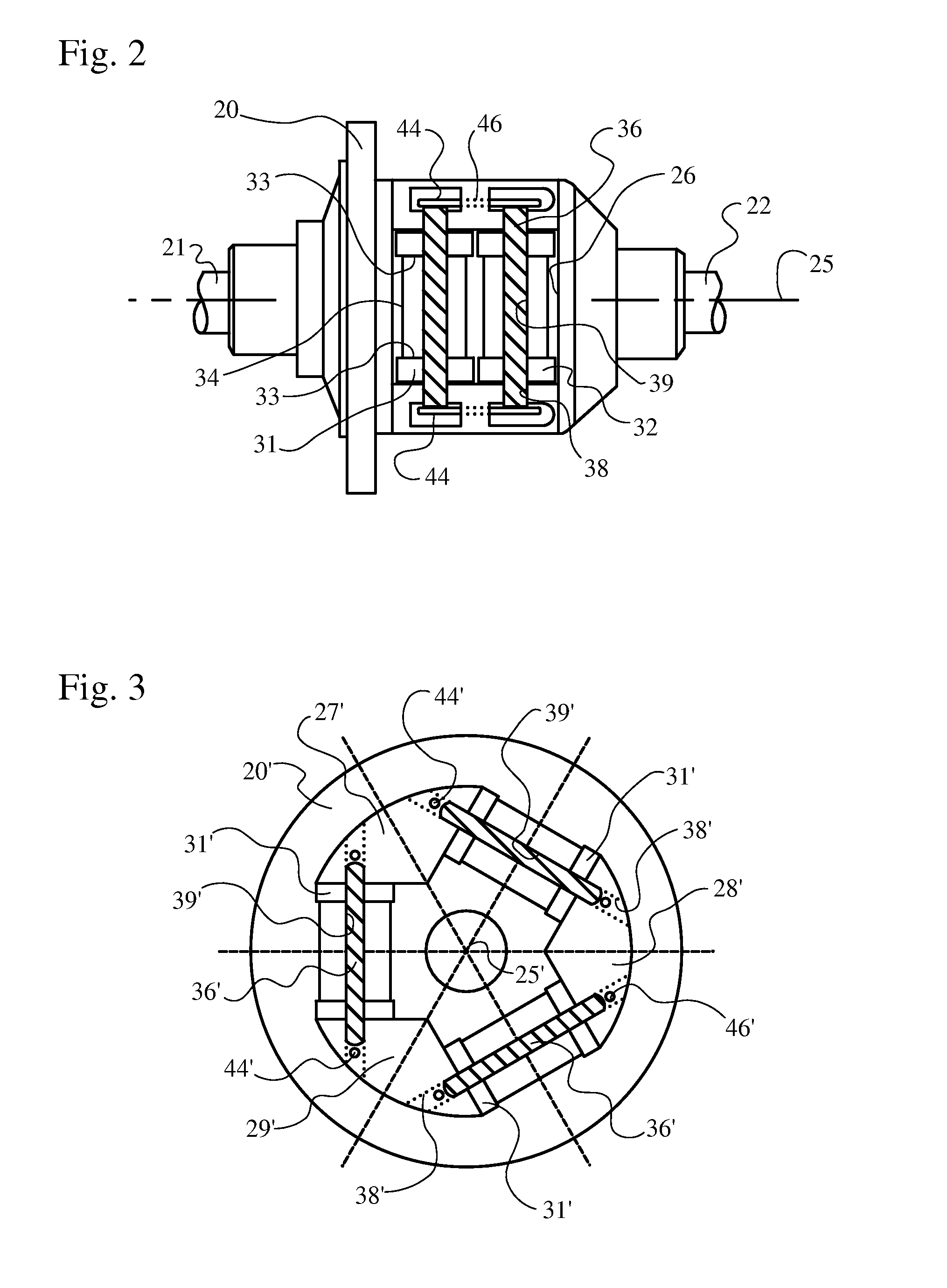
[0024]Preferably, the teeth of each side-gear worm have an involute profile but are cut with only plunge feed, while the teeth of the worm-wheel portions of the balance gears are helicoid worms having tip and root modifications made by a convex-shaped cutter. The side-gear worm teeth have a helix angle equal to or greater than 45° and significantly chamfered ends, and the gears are designed to provide a gear ratio between 1.5:1 and 2.5:1. The numbers of teeth in the (a) spur-gear portion and (b) worm-wheel portion of each balance gear, and (c) in each side-gear worm are all divisible by 2 or by 3, preferably by both 2 and 3. Further, any improperly positioned balance gear does not align properly with its respective mounting hole in the housing and, by merely rotating such a misaligned balance gear by one tooth in either direction, correct alignment and gear timing is achieved.

[0025]The new tooth design disclosed herein is best described as a “hybrid” between standard worm / worm-wheel...


PUM


Abstract

The compact, all-gear full-traction differential includes meshing pairs of side-gear worms and worm-wheel balance gears having a “hybrid” design. Preferably, the teeth of each side-gear worm have an involute profile but are cut with only plunge feed, while the teeth of the worm-wheel portions of the balance gears are helicoid worms having tip and root modifications made by a convex-shaped cutter. The side-gear worm teeth have a helix angle equal to or greater than 45° and significantly chamfered ends, and the gears are designed to provide a gear ratio between 1.5:1 and 2.5:1. The numbers of teeth in the spur-gear portion and worm-wheel portion of each balance gear and in each side-gear worm are all divisible by 2 or by 3, preferably by both 2 and 3.

Description

BACKGROUND OF THE INVENTION[0001]1. Field of the Invention[0002]This invention relates to all-gear differentials of the type commonly referred to as “limited-slip” designed primarily for automotive use and, more particularly, to such differentials designed for use in vehicles where efficiency, space, cost, and weight are critical.[0003]2. Description of Related Art[0004]While there are many types of limited-slip differentials, some of the most commercially successful have been the all-gear differentials based upon the designs of Vernon E. Gleasman, and the most efficient of these have been those based upon his crossed-axis design that has been identified commercially as the Torsen®-Type 1 differential. A recent improvement of such known limited-slip differentials using crossed-axis planetary gearing was disclosed in U.S. Pat. No. 6,783,476 (“Compact Full-Traction Differential”, assigned to the same assignee as the present invention and identified by the trademark “IsoTorque”), incor...

Claims


Application Information

Patent Timeline
Patent Type & Authority Applications(United States)
IPC IPC(8): F16H48/06F16H48/12
CPCF16H48/28Y10T407/173F16H48/29F16H48/12
Inventor GLEASMAN, KEITH E.GLEASMAN, JAMES Y.SUWIJN, PAUL W.
Owner TORVEC INC
Why Eureka
Try Eureka