This helps you quickly interpret patents by identifying the three key elements:
Problems solved by technology
Method used
Benefits of technology
[0016]It is one of the objects of the present invention is to provide a manipulator for medical use, capable of automatically locking a w
Problems solved by technology
The long incision site can be a significant concern because it is subject to inf
Method used
Image
Click on the blue label to locate the original text in one second.
Reading with bidirectional positioning of images and text.
Examples
first embodiment
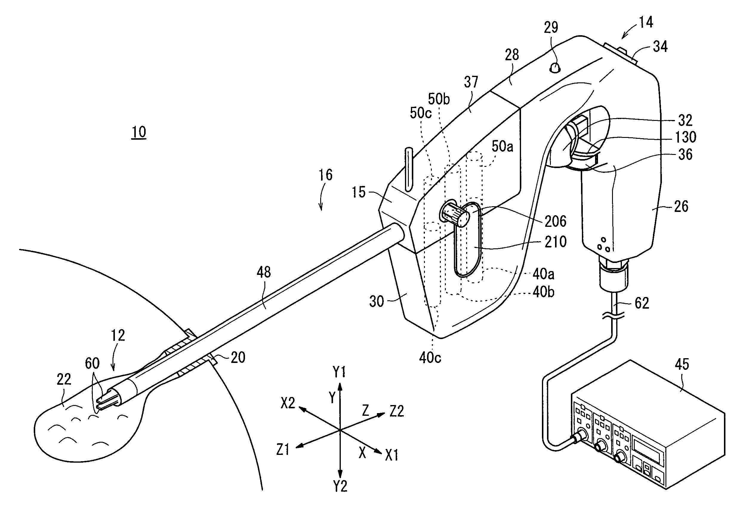
[0048]An end working portion 12 mounted on the distal end of the manipulator 10 serves to grip a portion of a living tissue, a curved needle, or the like for performing a certain operation, and is usually referred to as gripping forceps or a needle driver (needle holder).
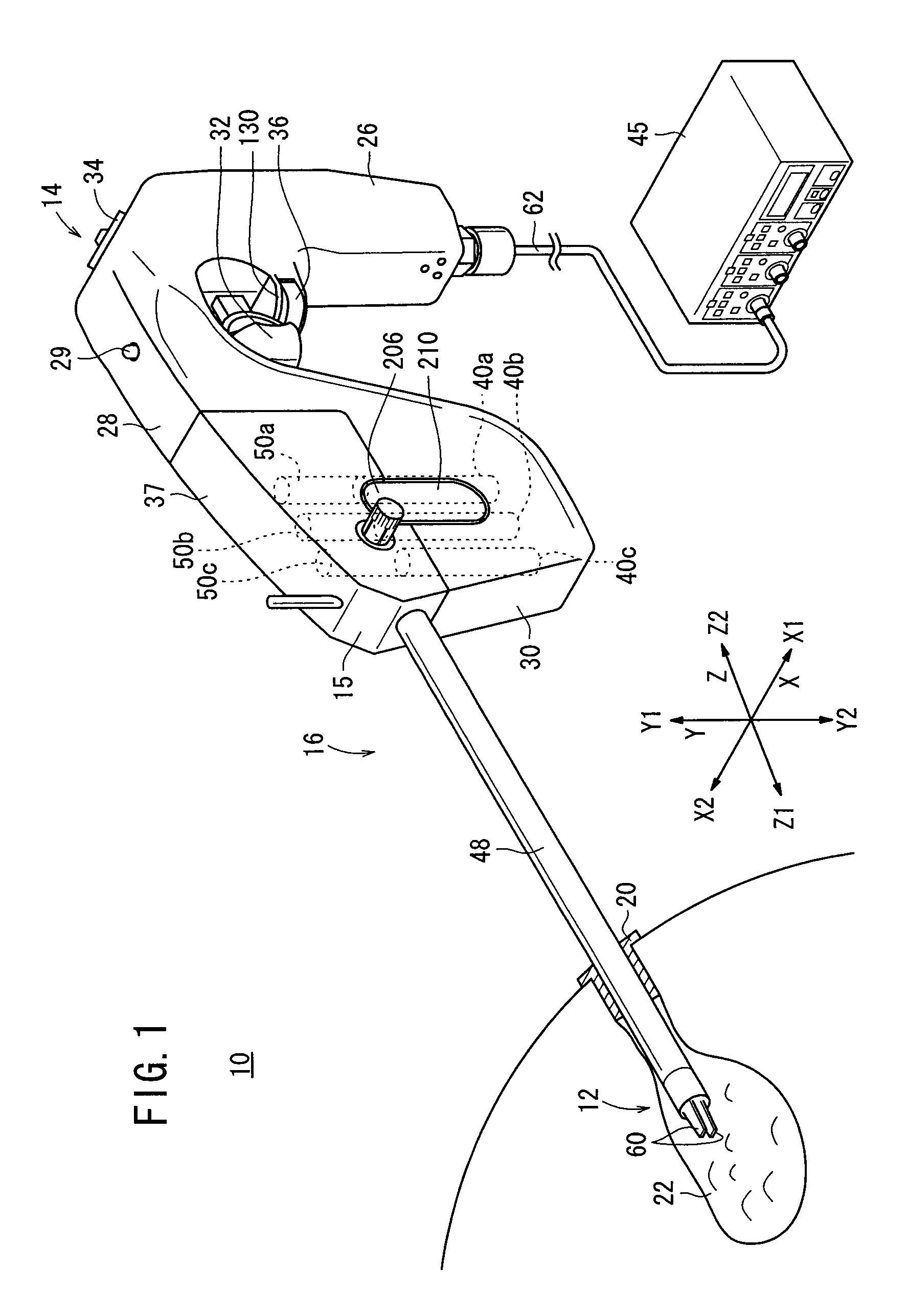
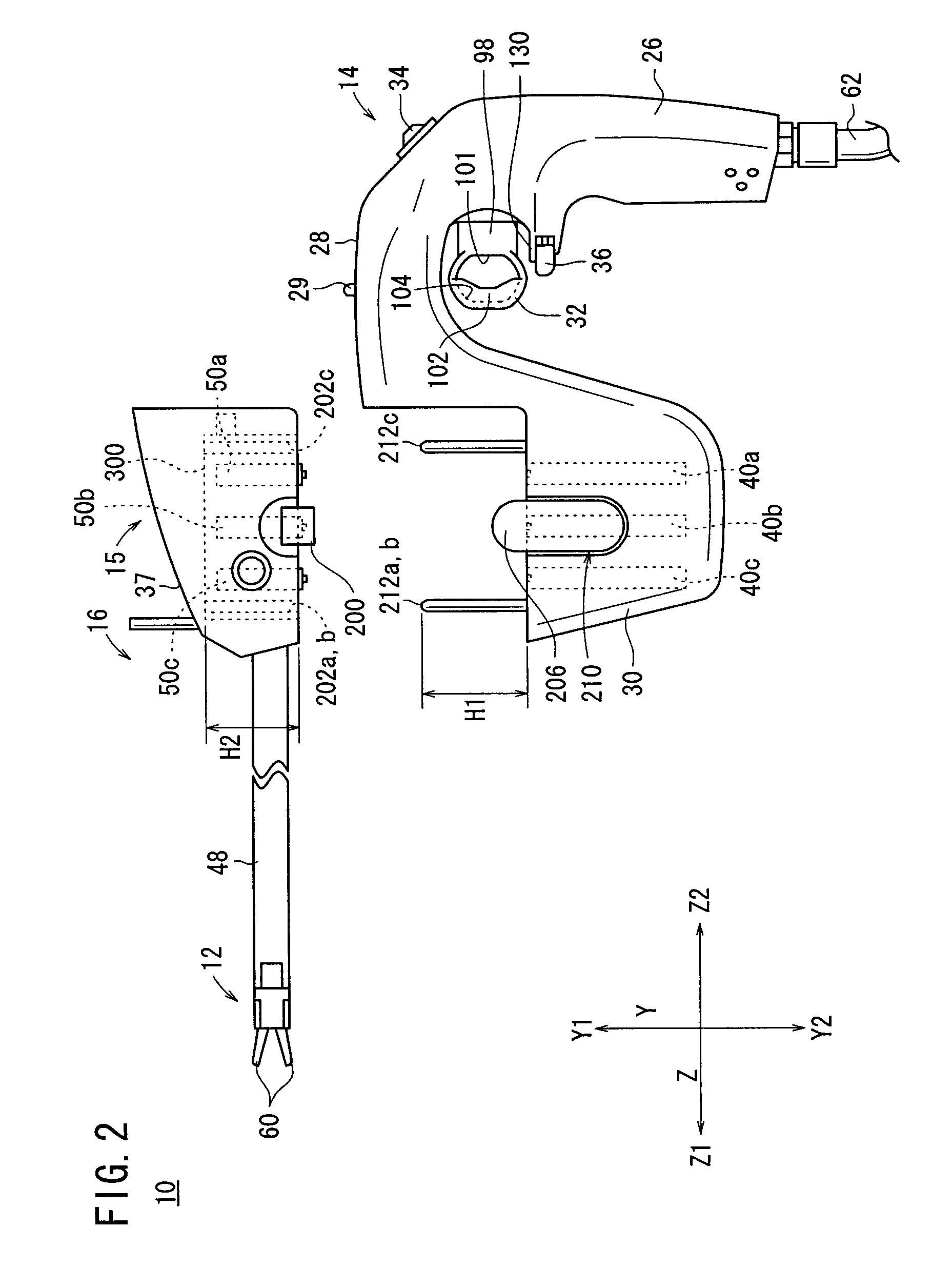
[0049]As shown in FIGS. 1 and 2, the manipulator 10 comprises an operation command unit 14 on a proximal end thereof which is held and operated by hand and a working unit 16 attachable to and detachable from the operation command unit 14.
[0050]It is assumed in the description which follows that the transverse direction of the manipulator 10 is referred to as X direction, vertical direction thereof as Y direction, and longitudinal directions of a connecting shaft 48 as Z direction in FIG. 1. Of the X directions, the rightward direction is referred to as an X1 direction, and the leftward direction as an X2 direction. Of the Y directions, the upward direction is referred to as a Y1 direction, and the downward directio...
second embodiment
[0113]Then, a medical manipulator system 1100 will be described below. First, components of the medical manipulator system 1100 and the corresponding components of the above-mentioned manipulator 10 will be described.
[0114]The main components of the medical manipulator system 1100: a manipulator 1102(a), a control unit 1104(b), a surgical instrument 1106(c), a surgical instrument control unit 1112(d), a surgical tool controller 1107(e), a surgical tool 1122(f), a shaft 1116(g), a handle 1110(h), a button 1114(i), a cable conduit 1115(j), a motor 1212(k), a locking plate 1402(l), a drive assembly 1204 and a surgical instrument connector 1400(m), a spring 1401(n), a surgical instrument control unit connector 1410(o), and a notched aperture 1800(p), correspond respectively to the components of the manipulator 10: the manipulator 10(a), the controller 45(b), the working unit 16(c), the actuator block 30(d), the connecting portion 15(e), the end working portion 12(f), the connecting sha...
PUM
Abstract
In a manipulator, an actuator block contains motors and rotary shafts extending from the motors. A working unit of the manipulator contains a connecting portion, attachable to and detachable from the actuator block. The connecting portion has pulleys connectable to ends of the rotary shafts, and has a locking plate movable by alignment pins. The locking plate has slits, which are engaged with plate-shaped portions formed on the upper ends of the pulleys. A coil spring is placed between the locking plate and a top plate.
Description
BACKGROUND OF THE INVENTION[0001]1. Field of the Invention[0002]The present invention relates to a manipulator for medical use having an actuator unit and a working unit removable therefrom.[0003]2. Description of the Related Art[0004]According to laparoscopic surgery, it is customary to form a plurality of holes in the abdominal part of the patient, insert an endoscope and a forceps (or a manipulator) into the respective holes, and perform the surgical operation while images captured by the endoscope are being observed on a display monitor by the surgeon. Since such a laparoscopic surgical operation does not require the abdominal cavity to be opened, the burden on the patient is small and the number of days which the patient needs to recover and spend in the hospital until they are allowed to come out of hospital is greatly reduced. For these reasons, the laparoscopic surgical operation is expected to find an increased range of applications.[0005]A manipulator system is composed of...
Claims
Application Information
Patent Timeline
Application Date:The date an application was filed.
Publication Date:The date a patent or application was officially published.
First Publication Date:The earliest publication date of a patent with the same application number.
Issue Date:Publication date of the patent grant document.
PCT Entry Date:The Entry date of PCT National Phase.
Estimated Expiry Date:The statutory expiry date of a patent right according to the Patent Law, and it is the longest term of protection that the patent right can achieve without the termination of the patent right due to other reasons(Term extension factor has been taken into account ).
Invalid Date:Actual expiry date is based on effective date or publication date of legal transaction data of invalid patent.