Method Of Cementing Expandable Well Tubing

a well tubing and cementing technology, applied in the direction of wellbore/well accessories, ceramicware, applications, etc., can solve the problems of difficult to achieve satisfactory mud displacement, new challenges in cementing, and cement often does not produce reliable seals, etc., to achieve suitable d, increase compressibility, and low viscosity

Inactive Publication Date: 2008-05-08
SCHLUMBERGER TECH CORP
View PDF4 Cites 11 Cited by
  • Summary
  • Abstract
  • Description
  • Claims
  • Application Information

AI Technical Summary

Benefits of technology

[0014]The method is preferably applied as a sub-operation within the cementing of a casing string in a section of the well. As such the injection of the sealant is preferably preceded by a step of injecting a cement composition. The sealant is pumped as a fluid directly after the cement, and sets quickly to a deformable material. It is advantageous to select the setting time of the cement composition to be substantially longer than the setting time of the sealant composition. Thus the sealant has already formed a solid matrix around the casing shoe before the expansion of the tubing starts, while the cement can still be squeezed by the expanding tubing. Then the sealant can provide a reliable seal in a suitable stress state at the shoe of the casing, and a complete cement matrix can be placed throughout the rest of the well annulus.
[0015]The casing expansion process offers a method by which a deformable sealant material can be put into a state of compressive stress. In a preferred method this invention provides a sealant composition which includes microspheres or gas-producing blowing agents. If, for example the expansion of the tubing is substantially greater than that which would be required to bring the cladding into contact with the wellbore wall additives such as malleable microspheres can be used to increase the compressability.
[0016]Many liquid elastomer precursors could potentially be used as sealant fluid such as silicones, polysulphides, polyurethanes, polybutadienes and the like. The preferred fluid composition according to the invention is based on mixtures of poly(propylene glycol) diglycidyl ether and trimethylol propane triglycidyl ether, which can be crosslinked with typical epoxy resin crosslinkers such as diamines, amidoamines or polyamines. The setting time of the fluid can be controlled by the choice of crosslinker and / or by the addition of accelerating or retarding agents. The preferred fluid composition gives a very low viscosity starting material which sets to an elastomeric material with suitable deformability for the expansion. Fillers and weighting agents such as barium sulphate, iron oxide, galena or manganese dioxide can be added to raise the density of the material to a suitable level.
[0017]The present invention is particularly suited for operations which require a repeated expansion of the casing shoe, and thus enables the drilling of monodiameter wells.

Problems solved by technology

However, cement often does not produce a reliable seal because it is a rigid and brittle material and because standard placement techniques do not provide a mechanism whereby it can be set into a suitable state of stress.
Expandable tubing pose new challenges for cementing.
After expansion, the annulus between the tubing and the borehole is very narrow, which makes it very difficult to achieve satisfactory mud displacement if cement is pumped at this stage.
The cement must therefore have an unusually long thickening time, as extra time must be allowed to carry out the expansion.
It is common practice to cement only the lower portion of each section in this way; if the whole annulus is cemented then an even longer thickening time is required, and this leads to excessively long wait-on-cement times in order to operate in a safe window.
However, cementing only the lower section of the casing carries risks also, since it leaves the bulk of the casing unsupported and unprotected against corrosion by formation fluids, and reduces the probability of achieving zonal isolation.
Furthermore, since the cladding increases the external diameter of the tubing prior to expansion, it restricts the size of tubing that can be successfully deployed through the previous casing and thus compromises one of the main advantages of the expandable technology.
However, this will result at best in the loss of compression of the cladding, and it is not explained how the existing fluid in the wellbore will be displaced by this process.
The filling of the entire annulus with such a material is likely to be prohibitively expensive, but the filling of the annulus only in the region of the shoe leaves the rest of the tubing unsupported and vulnerable to corrosion as described previously.
In order to make the material sufficiently deformable to allow for the compression the quantity of latex is more than double that of the cement, which results in a very weak product which is likely to be considerably more permeable than conventional cement both as a result of the foam and the low solid volume fraction of the fluid itself.
This material could potentially be used to cement the whole length of the annulus, but given its very large proportion of latex this is also likely to be prohibitively expensive.

Method used


Image

  • Method Of Cementing Expandable Well Tubing
  • Method Of Cementing Expandable Well Tubing
  • Method Of Cementing Expandable Well Tubing

Examples


Embodiment Construction

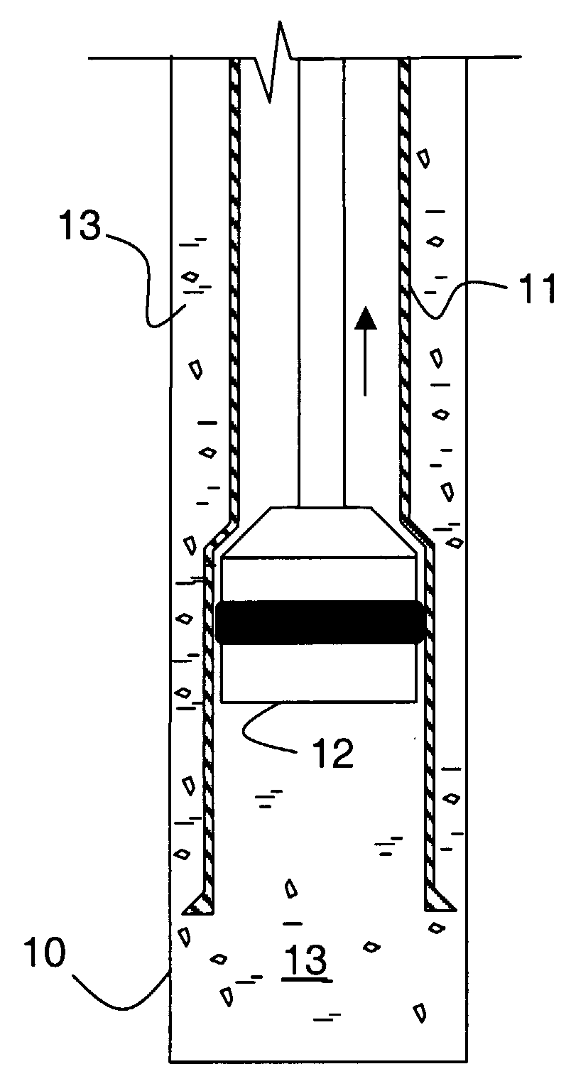
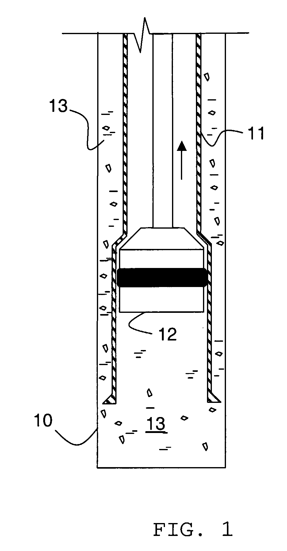
[0023]Before describing an example of the present invention, the basic expandable liner operation as known is illustrated with reference to FIG. 1. There is shown the bottom section 10 of an open borehole. In the open hole a solid expandable liner 11 is run through existing casing or liner, positioned in the open hole 10, then expanded using a mandrel or expansion cone 12 from the bottom up. At the top (not shown) the expansion cone 12 reaches the overlap between the expandable open hole liner 11 and existing pipe string (not shown), the cone expands a special hanger joint to provide a permanent seal between the two strings. The annulus between the borehole 10 and the liner 11 is filled with cement material 13, which after setting is designed to provide a seal between the formation and the liner.

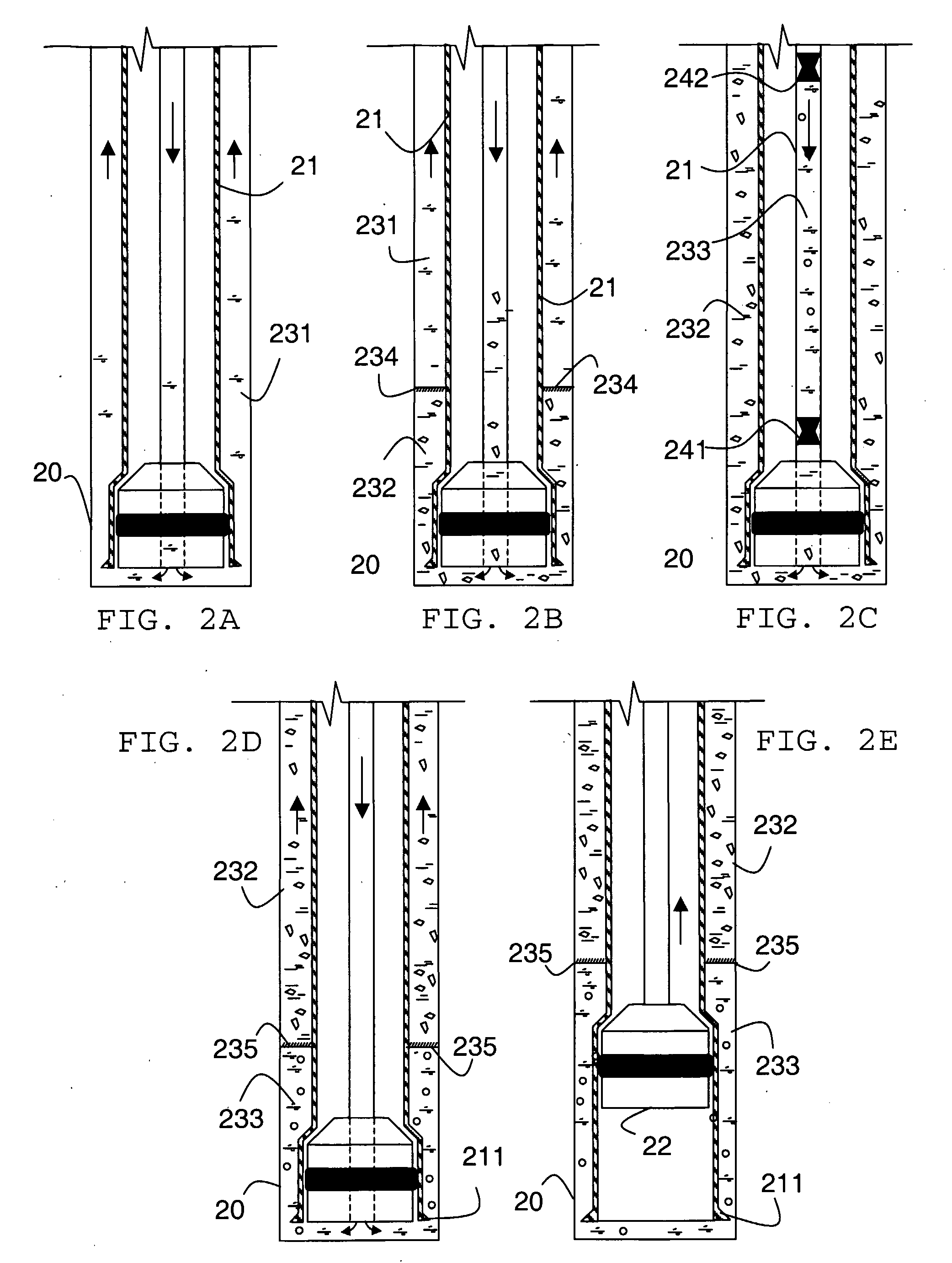
[0024]Detailing now steps in accordance with an example of the invention, FIG. 2A shows a drilled hole 20 filled with drilling fluid 231. An expandable tubing (casing) 21 is first lowered in...


PUM

PropertyMeasurementUnit
temperatureaaaaaaaaaa
plastic viscosityaaaaaaaaaa
yield stressaaaaaaaaaa

Abstract

The invention describes a method of lining a well using expandable tubing including the steps of lowering a expandable tubing in a well bore; injecting a sealant composition into said well; letting the sealant composition solidify into a deformable matrix embedding at least a bottom section of said tubing within said well; and expanding the tubing. The invention allows the creation of a high quality seal at the shoe of the expandable casing because the deformable material is highly stressed by the expansion, and it also allows for the rest of the casing to be properly supported and protected by conventional cement, without incurring excessive wait-on-cement times.

Description

CROSS-REFERENCE TO RELATED APPLICATIONS[0001]This application claims the benefits of priority from:[0002]i) Application Number 0424712.8, entitled “METHOD OF CEMENTING EXPANDABLE TUBULARS,” filed in the United Kingdom on Nov. 9, 2004; and[0003]ii) Application Number PCT / GB2005 / 004308, entitled “METHOD OF CEMENTING EXPANDABLE WELL TUBING,” filed under the PCT on Nov. 8, 2005;All of which are commonly assigned to assignee of the present invention and hereby incorporated by reference in their entirety.[0004]The invention describes a method for cementing expandable tubing, particularly wellbore tubing in the exploration and production of hydrocarbon reservoirs.BACKGROUND OF THE INVENTION[0005]Conventional oil and gas wells have to be drilled in multiple sections in order to ensure that the hydrostatic pressure in the section being drilled lies between the pore and fracture pressures of the surrounding formations. After drilling each section a casing is lowered into place and the annulus...

Claims


Application Information

Patent Timeline
Patent Type & Authority Applications(United States)
IPC IPC(8): E21B33/13C04B26/10C09K8/44C09K8/473E21B33/14E21B43/10
CPCC04B26/10C04B2111/503C09K8/44C09K8/473E21B33/14E21B43/103C04B14/301C04B38/02
Inventor PHIPPS, JONATHANDESROCHES, JEANJAMES, SIMONGUILLOT, DOMINIQUE
Owner SCHLUMBERGER TECH CORP
Why Eureka
Try Eureka