Automotive vehicle employing kinetic energy storage/reuse capability

a technology of kinetic energy storage and automotive vehicles, which is applied in the direction of propulsion parts, electric propulsion mounting, transportation and packaging, etc., can solve the problems of high overall price of automobiles, questionable customers' money saving, and high cost of motor/generator, etc., to achieve low overall weight, low cost, and high kinetic energy-converting efficiency

Inactive Publication Date: 2008-05-08
HU LOONG CHIANG
View PDF9 Cites 31 Cited by
  • Summary
  • Abstract
  • Description
  • Claims
  • Application Information

AI Technical Summary

Benefits of technology

[0011]Therefore, the main object of the present invention is to provide an automotive vehicle that may be m

Problems solved by technology

Though the conventional hybrid automobile achieves the purpose of saving energy, especially when the vehicle is started or during low-speed driving, there are still many drawbacks associated with the conventional hybrid automobile.
1. The cost of the motor/generator is rather high, which results in high overall price for the automobiles. Hence the purpose of saving money for customers is questionable.
2. The present technology is such that efficiency in converting kinetic energy through the motor/generator into electric energy in the batteries is low. Moreover, even when the automobile is idle, electric energy stored in the batteries discharging due to the natural characteristics of batteries, and hence stored electrical energy targeted for reuse is gradually dissipated.
3. High-powered batteries are

Method used


Image

  • Automotive vehicle employing kinetic energy storage/reuse capability
  • Automotive vehicle employing kinetic energy storage/reuse capability
  • Automotive vehicle employing kinetic energy storage/reuse capability

Examples


Embodiment Construction

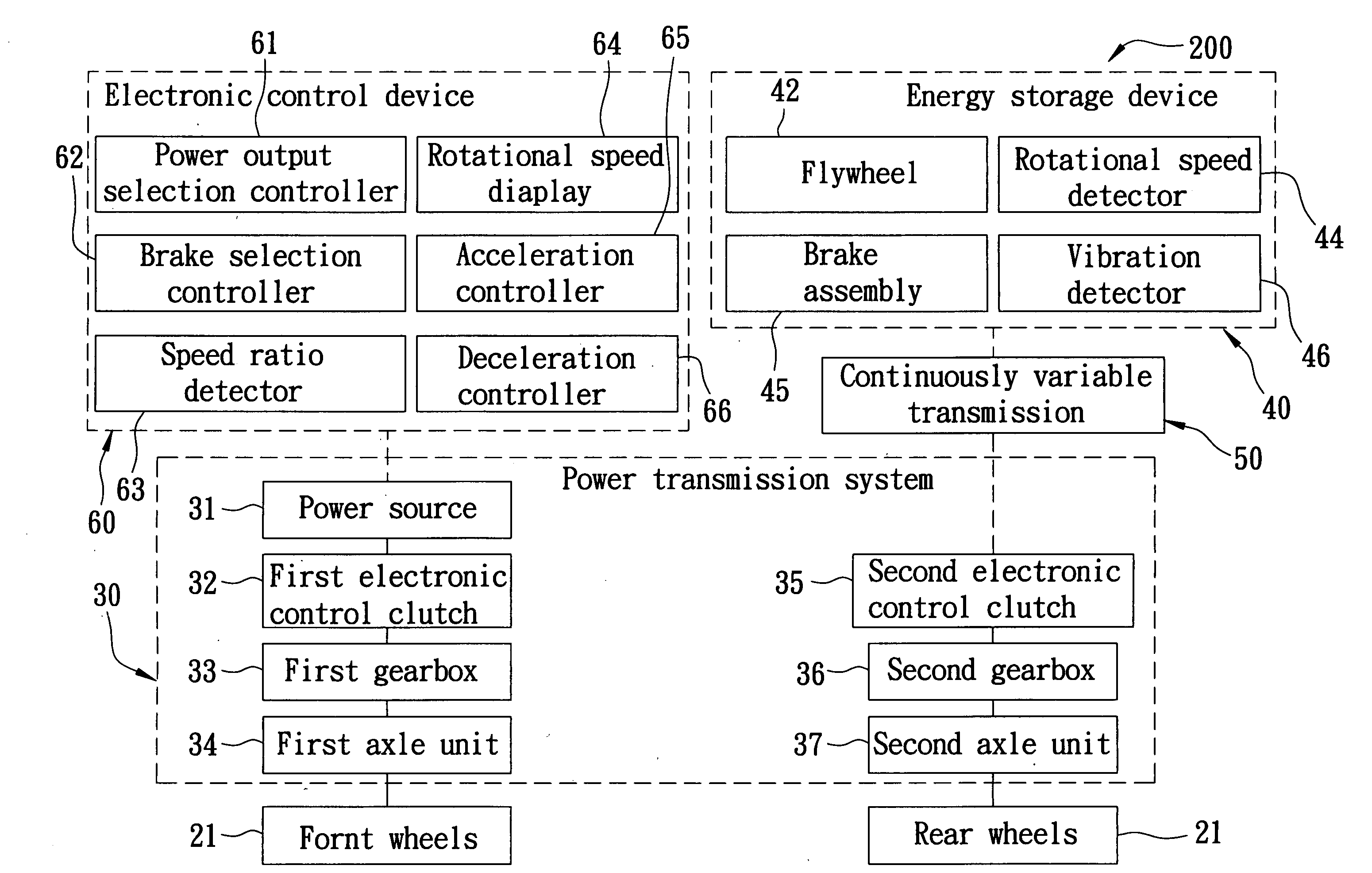
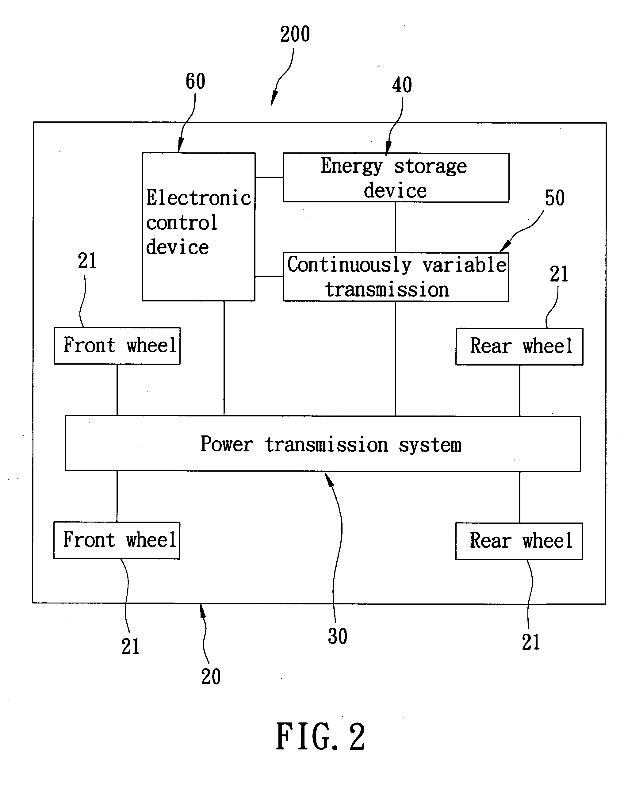
[0045]Referring to FIGS. 2 and 3, the first preferred embodiment of an automotive vehicle 200 according to the present invention is shown to include a vehicle body 20, a power transmission system 30, an energy storage device 40, a continuously variable transmission 50, and an electronic control device 60.

[0046]The vehicle body 20 includes a wheel unit.

[0047]The power transmission system 30 is mounted in the vehicle body 20, connected to the wheel unit, and includes a power source 31 for driving the wheel unit, a first electronic control clutch 32 connected to the power source 31, a first gearbox 33 connected to the first electronic control clutch 32, a first axle unit 34 connected to the first gearbox 33, a second electronic control clutch 35 connected to the continuously variable transmission 50, a second gearbox 36 connected to the second electronic control clutch 35, and a second axle unit 37 connected to the second gearbox 36.

[0048]The power source 31 may be an engine or a motor...


PUM


Abstract

An automotive vehicle includes a vehicle body, a power transmission system, an energy storage device, a continuously variable transmission, and an electronic control device. The power transmission system includes a power source for driving the automotive vehicle. The energy storage device includes a flywheel. The continuously variable transmission interconnects the power transmission system and the energy storage device. When the automotive vehicle decelerates, the electronic control device connects the flywheel to the power transmission system through the continuously variable transmission, and transfers energy of the power transmission system to the flywheel. When the automotive vehicle accelerates and the electronic control device connects the flywheel to the power transmission system through the continuously variable transmission, energy of the flywheel is transferred to the power transmission system.

Description

BACKGROUND OF THE INVENTION[0001]1. Field of the Invention[0002]The invention relates to an automotive vehicle, more particularly to an automotive vehicle having a flywheel energy storage device.[0003]2. Description of the Related Art[0004]Referring to FIG. 1, a conventional hybrid automobile utilizes gasoline and batteries as power source, and employs a control unit to control an electronic control switching clutch so as to switch power to be outputted from either an engine or a motor / generator, thereby achieving the purpose of selecting different power sources in accordance with different needs. For instance, when an automobile is driven at a low speed, the motor / generator is first used as the power source, and when later a high speed is desired, the engine is chosen as the power source. Hence, in this manner, fuel economy is achieved. With respect to restocking battery power, kinetic energy is converted through the motor / generator into stored electrical energy during braking for ...

Claims


Application Information

Patent Timeline
IPC IPC(8): B60K1/00
CPCB60K6/105B60K6/30B60K6/52B60K6/543B60L2240/486B60W10/02Y02T10/6265B60W20/00B60W2510/1015B60W2540/10B60W2540/12Y02T10/6204B60W10/101Y02T10/90Y02T10/62B60K6/20B60K6/10B60K6/34
Inventor HU, LOONG-CHIANG
Owner HU LOONG CHIANG
Why Eureka
Try Eureka