System and method of manufacturing sputtering targets

Inactive Publication Date: 2008-05-08
SPUTTERING MATERIALS
View PDF21 Cites 24 Cited by
  • Summary
  • Abstract
  • Description
  • Claims
  • Application Information

AI Technical Summary

Benefits of technology

[0009]increased conductivity between the target and the backing plate;
[0010]enhanced operation of the target during sputtering due

Problems solved by technology

However, these methods can provide limitation on the shape of sputter targets produced.
Target assemblies bonded using the prior art methods hav

Method used


Image

  • System and method of manufacturing sputtering targets
  • System and method of manufacturing sputtering targets
  • System and method of manufacturing sputtering targets

Examples


Embodiment Construction

[0005]Advantages of One or More Embodiments of the Present Invention

[0006]The various embodiments of the present invention may, but do not necessarily, achieve one or more of the following advantages:

[0007]increased bonding between the target and the backing plate;

[0008]reduced delamination between the target and the backing plate or substrate;

[0009]increased conductivity between the target and the backing plate;

[0010]enhanced operation of the target during sputtering due to the increased bonding between the target and the backing plate;

[0011]increased selectivity in the shape of the target assembly;

[0012]reduced contamination of the target; and

[0013]controlled purity of the target.

[0014]These and other advantages may be realized by reference to the remaining portions of the specification, claims, and abstract.

BRIEF DESCRIPTION OF ONE EMBODIMENT OF THE PRESENT INVENTION

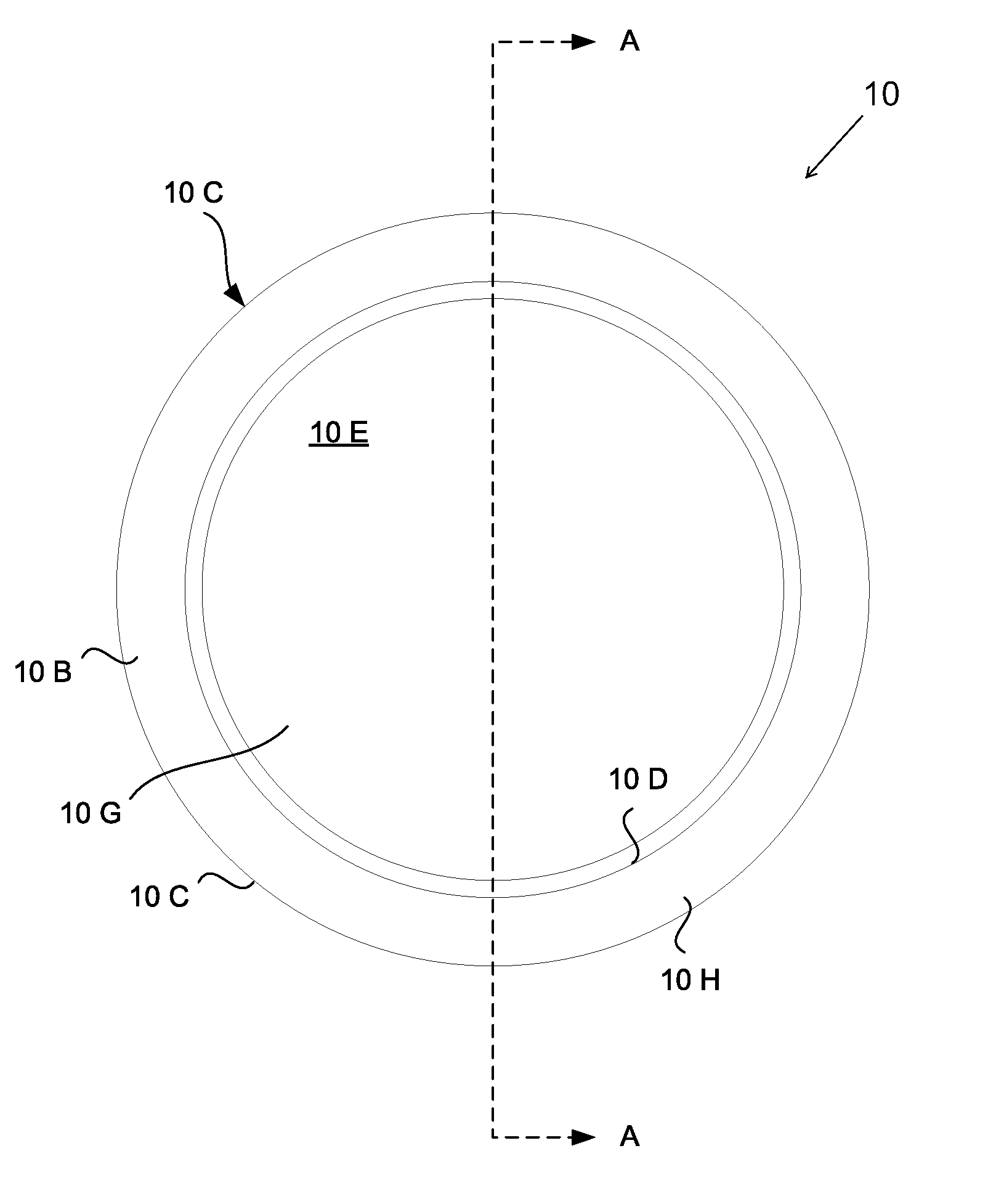
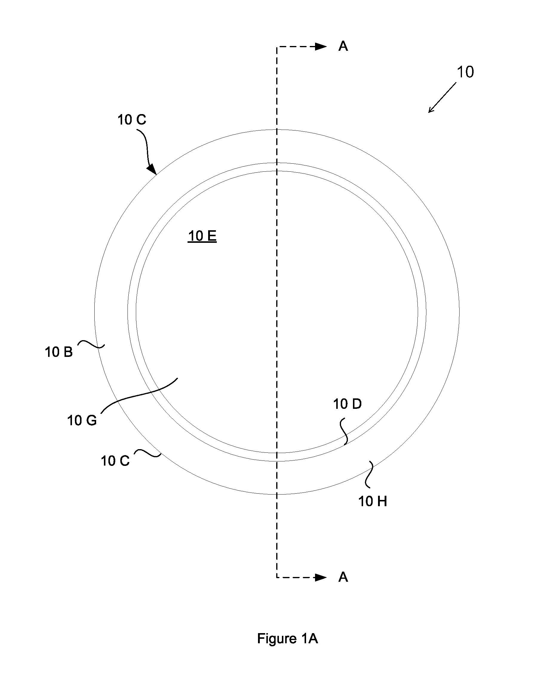
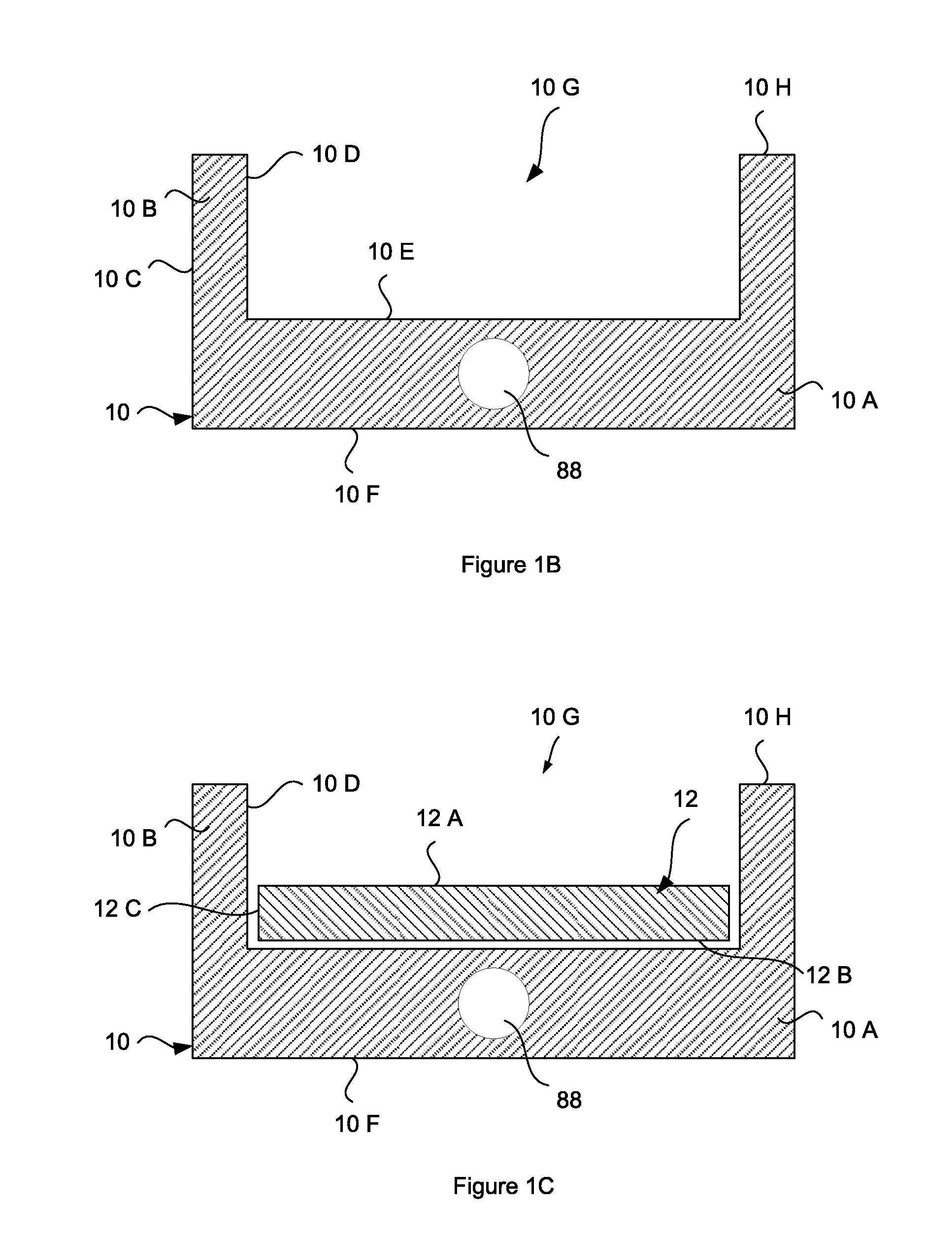
[0015]The present invention provides a method of manufacturing a sputtering target. The method includes depositing...


PUM

PropertyMeasurementUnit
Temperatureaaaaaaaaaa
Thicknessaaaaaaaaaa
Melting pointaaaaaaaaaa

Abstract

A method for manufacturing a sputtering target assembly that is used with a sputtering deposition machine. A molten target material is deposited onto a substrate or backing plate to form a target assembly. The target assembly is heated to approximately the melting point temperature of the target material in order to form an alloy interface layer between the substrate and the target material that improves the bond strength of the target assembly. In one embodiment, the thickness of the alloy interface layer can be controlled by cooling the substrate during the formation of the alloy interface layer.

Description

CROSS REFERENCE TO RELATED APPLICATIONS[0001]This application claims priority to U.S. provisional patent application Ser. No. 60 / 864,968, filed 8 Nov. 2006, the contents of which are herein incorporated by reference.FIELD OF THE INVENTION[0002]The present invention relates to sputtering target assemblies and other metal articles, as well as methods of making the same. More particularly, the present invention relates to methods to bond various metals together to form bonded sputtering target assemblies and other bonded articles.BACKGROUND OF THE INVENTION[0003]In a sputtering process, a target material is subject to bombardment by energetic ions. In a sputtering process using a multi-constituent target, each constituent may sputter at a different rate. Therefore, in order to produce a sputtered film with the constituents in the correct ratio, it is important that the target material have specific proportions of the constituent materials.[0004]Typically, the target material is first f...

Claims


Application Information

Patent Timeline
IPC IPC(8): C23C14/34
CPCC23C14/3407
Inventor PURDY, CLIFFORD C.HOWARD, GREGORY M.
Owner SPUTTERING MATERIALS
Why Eureka
Try Eureka