Rotary Seal

a technology of rotary seals and seal faces, applied in the direction of engine seals, engine components, mechanical equipment, etc., can solve the problems of loss of hermetic seals, heat generation and/or seal face deterioration, complex labyrinth design cannot hold fluid levels,

Inactive Publication Date: 2008-05-08
AES ENG
View PDF9 Cites 10 Cited by
  • Summary
  • Abstract
  • Description
  • Claims
  • Application Information

AI Technical Summary

Benefits of technology

[0024]Accordingly, it is preferred that, adjacent to the hermetic seal face, there is a radially and / or longitudinally extending cavity which captures and retains coalesced oil from the oil mist. In effect, the function of the textured seal face is to promote the coalescence of the oil mist by energising the fluid so that it can be put into communication with the hermetic seal face.

Problems solved by technology

When the equipment is static, the complex labyrinth design is unable to hold a fluid level which, in horizontal application, is at a higher radial level than the inlet position of the protector.
In marginal lubrication applications the fluid film is typically very thin which may cause heat generation and / or seal face deterioration.
Seal face deterioration will lead to loss of the hermetic seal.
However 0.3 cc / hr velocity is insufficient to adequately lubricate and cool a mechanical seal face and therefore a conventional mechanical seal face bearing protection solution may fail to function correctly under such conditions.
Unfortunately, a non-contacting bearing protector, by its nature, has an oil mist escape path between the counter rotating components.
This leads to oil mist being evacuated into the environment.
Not only does this lead to loss of oil and therefore significantly increases the running cost of the supply unit, in many parts of the world, the environmental issues are unacceptable.

Method used


Image

  • Rotary Seal
  • Rotary Seal
  • Rotary Seal

Examples


first embodiment

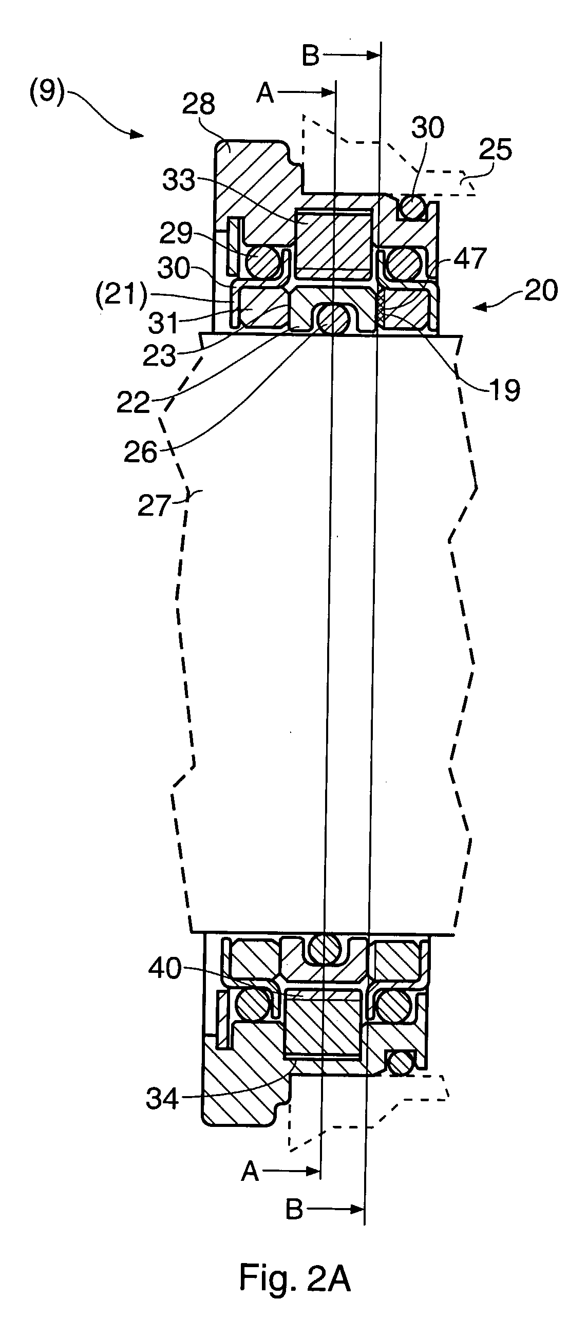
[0062]FIG. 2A is a longitudinal cross-section of the invention, showing a dual bearing protection mechanical seal 9 with one textured seal face 19 adjacent to the sealed fluid 20. The sealed fluid 20 is an oil mist in this example. However, it could be any marginal lubrication media including grease, powder or a slurry combination.

[0063]The mechanical seal 9 includes a stationary and axially floating seal face assembly 21 which is magnetically spring biased towards a static rotary seal face 22. Rotary seal face 22 slides on static seal face 21, the interface between the seal faces forming a sealing area 23. This sealing area 23 is the primary seal that prevents fluid medium 20 from escaping from the bearing chamber 25.

[0064]Fluid medium 20 is also sealed by a rotary elastomer 26 which contacts shaft 27, thereby forming a first secondary sealing area. A second secondary sealing area is formed between stationary seal face 21 and stationary housing 28 by means of elastomeric member 29....

second embodiment

[0079]FIG. 4 is a longitudinal section of the invention, showing one textured seal face 70 adjacent to the atmospheric side of the bearing cavity 71.

third embodiment

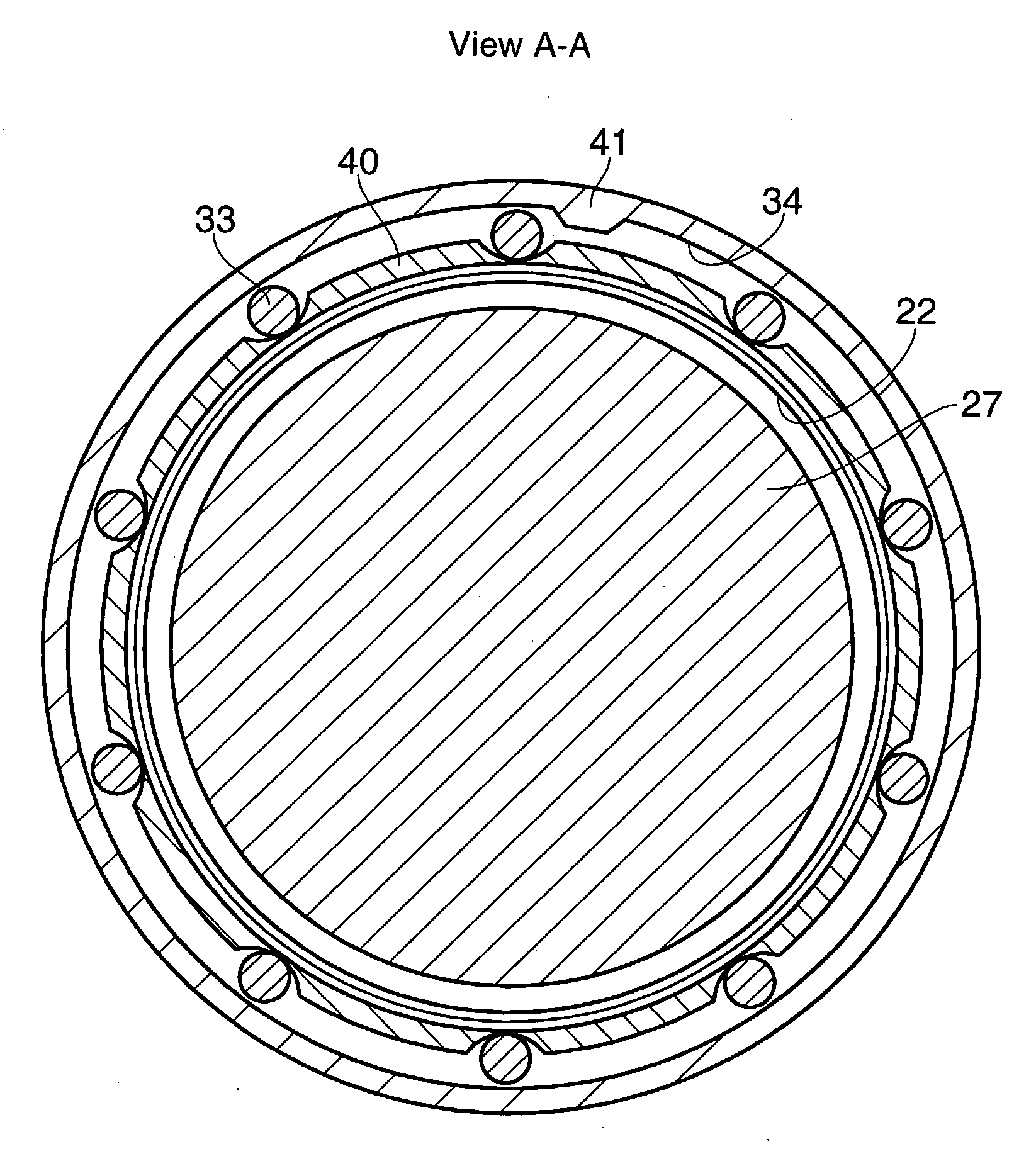
[0080]FIG. 5 corresponds to FIG. 2A and shows the end view of the textured seal face 47 on line B-B of the The position of the entrapped oil pool 53 is clearly shown.

[0081]FIG. 6 is a partial longitudinal section of the fourth embodiment of the invention, showing the two sets of textured seal faces 80 and 81 of the first and second embodiments, albeit textured seal face 81 is only partially textured across its radial width. Any combination of the first, second and fourth embodiments could be provided with any combination of patterns and by any suitable combination of marking, engraving, texturing, and etching techniques of either seal face in the seal assembly.

[0082]An example is shown in FIG. 7A which is an end view of an alternative textured seal face, on line E-E of FIG. 6. FIG. 7B shows an end view of the partially textured seal face 82, on line D-D of FIG. 6. Preferably, the partial texture 82 extends from the region of the face in contact with the oil pool. In the case of FIG...


PUM


Abstract

A rotary seal has a floating seal face in a sealing relationship with a stationary seal face, and a fluid collection cavity adjacent the floating seal face and the stationary seal face. The seal further includes a device for introducing a lubricant into the vicinity of the fluid collection cavity and a device for promoting coalescence of the lubricant, so that the lubricant accumulates in the fluid collection cavity and lubricates the seal faces.

Description

FIELD OF THE INVENTION[0001]This invention relates to rotary seals and is concerned with their use in rotating equipment and especially devices which prevent the ingress of a fluid or solid to an area which results in deterioration of equipment life. Such devices are often referred to as bearing protectors or bearing isolators. However, the use of such rotary seals extends well beyond the protection of a bearing in rotating equipment. Accordingly, while reference will be made below to bearing protectors, it should be understood that this term is used, as far as the invention is concerned, in connection with mechanical and other seals having wider uses.BACKGROUND TO THE INVENTION[0002]The purpose of a bearing protector is to prevent the ingress of fluid, solids and / or debris entering a bearing arrangement and thereby prevent the failure of the bearing. Bearing protectors generally fall into two categories: repeller or labyrinth bearing protectors; and mechanical seal bearing protecto...

Claims


Application Information

Patent Timeline
Patent Type & Authority Applications(United States)
IPC IPC(8): F16J15/34F16J15/44
CPCF16J15/441F16J15/3404F16J15/3408F16J15/3412
Inventor RODDIS, ALAN JAMESCOLVERSON, ANDREW
Owner AES ENG
Why Eureka
Try Eureka