Brake control apparatus and method

a technology of brake control and control apparatus, which is applied in the direction of braking systems, instruments, analogue processes for specific applications, etc., can solve the problems of reducing the pressure of the wheel cylinder, and the driver feeling some so as to reduce the discomfort in the braking feel

Inactive Publication Date: 2008-05-08
TOYOTA JIDOSHA KK
View PDF3 Cites 22 Cited by
  • Summary
  • Abstract
  • Description
  • Claims
  • Application Information

AI Technical Summary

Benefits of technology

[0007] The invention provides a brake control apparatus and method that reduces discomfort in a braking feel which may be caused when the control mode is changed.
[0009] According to the aspect of the invention described above, when the hydraulic pressure in the manual hydraulic pressure source is equal to or higher than the hydraulic pressure in the wheel cylinder, the control mode is changed from the control mode in which the hydraulic pressure applied to the wheel cylinder is controlled by the wheel cylinder pressure control system to the control mode in which the hydraulic fluid is supplied from the manual hydraulic pressure source to the wheel cylinder. Because the hydraulic pressure in the manual hydraulic pressure source is equal to or higher than the hydraulic pressure in the wheel cylinder, the situation does not occur in which the hydraulic fluid flows back from the wheel cylinder to the manual hydraulic pressure source when the control mode is changed and therefore the wheel cylinder pressure is decreased. Accordingly, even if the control mode is changed, for example, while the vehicle is stopped on a slope, occurrence of the situation in which the vehicle moves downward due to a reduction in the braking force is minimized. In addition, even if the control mode is changed while the vehicle is moving, discomfort in a braking feel is suppressed.
[0010] The brake control apparatus according to the aspect of the invention described above may further include a manual hydraulic pressure sensor that detects the hydraulic pressure in the manual hydraulic pressure source; and a wheel cylinder pressure sensor that detects the hydraulic pressure in the wheel cylinder. The control unit may determine that the condition that the hydraulic pressure in the manual hydraulic pressure source is equal to or higher than the hydraulic pressure in the wheel cylinder is satisfied, when the hydraulic pressure difference, which is obtained by subtracting the hydraulic pressure detected by the wheel cylinder pressure sensor from the hydraulic pressure detected by the manual hydraulic pressure sensor, is equal to or greater than a threshold value. In this way, it is possible to reliably determine whether the hydraulic pressure in the manual hydraulic pressure source is higher than the hydraulic pressure in the wheel cylinder by appropriately set the predetermined value as a margin.
[0020] According to the invention, it is possible to reduce discomfort in a braking feel.

Problems solved by technology

When the hydraulic pressure source is changed from the power hydraulic pressure source to another hydraulic pressure source, the wheel cylinder pressure may be decreased due to the pressure difference between the upstream side and downstream side of the control valve, which causes the driver to feel some discomfort in a braking feel.

Method used


Image

  • Brake control apparatus and method
  • Brake control apparatus and method
  • Brake control apparatus and method

Examples


Embodiment Construction

[0026] Hereafter, an embodiment of the invention will be described in detail with reference to the accompanying drawings.

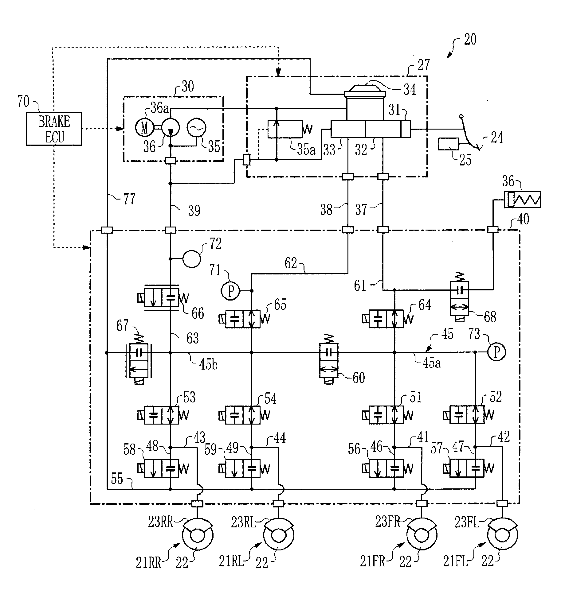
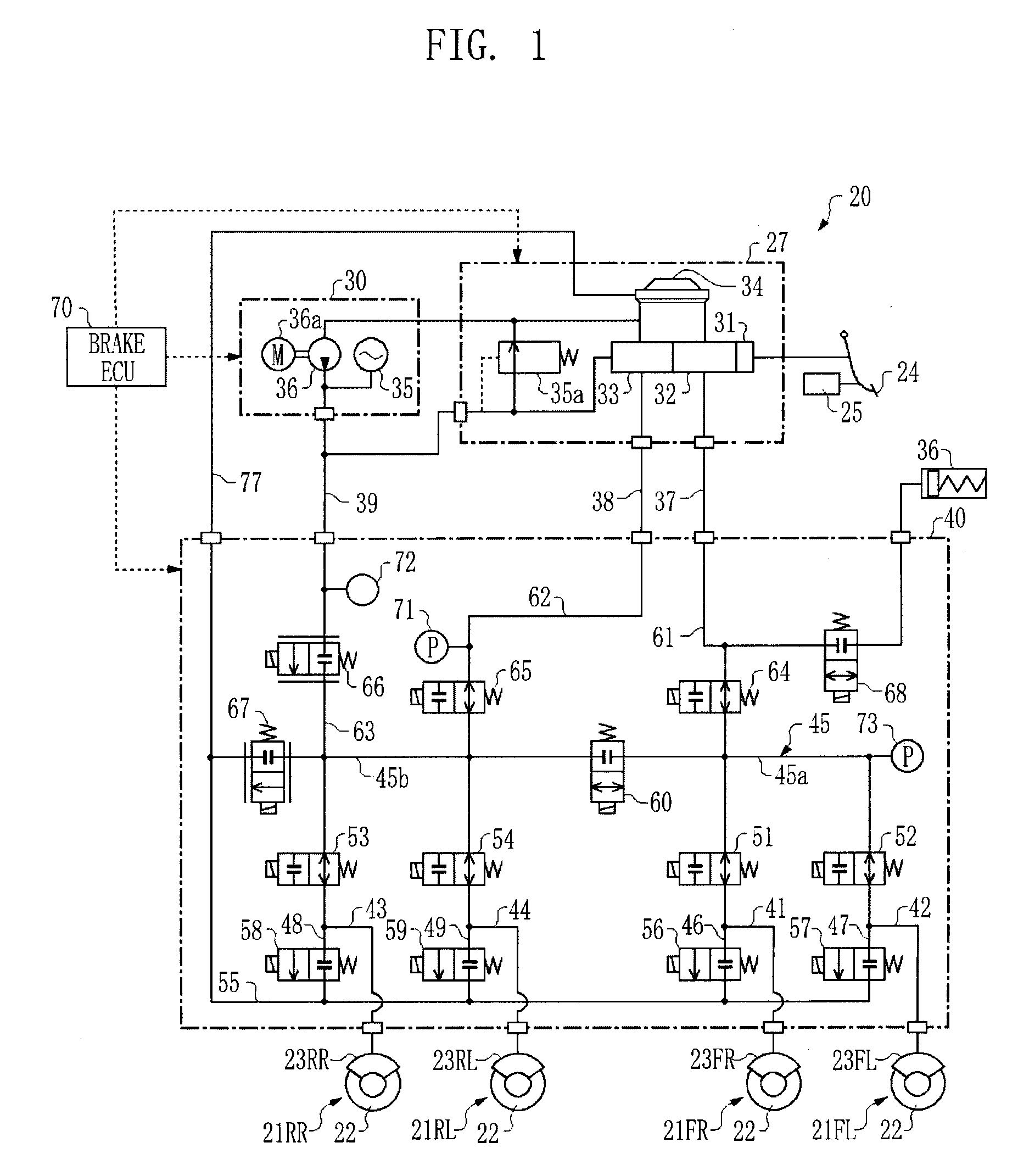
[0027]FIG. 1 is a system diagram showing a brake control apparatus 20 according to an embodiment of the invention. The brake control apparatus 20 shown in FIG. 1 forms an electronically-controlled brake system (ECB) for a vehicle, and controls braking forces applied to the four wheels of the vehicle. The brake control apparatus 20 according to the embodiment of the invention may be mounted in, for example, a hybrid vehicle which includes an electric motor and an internal combustion engine as drive power sources. In such hybrid vehicle, each of the regenerative braking control, in which the vehicle speed is reduced by converting some of kinetic energy of the vehicle into electrical energy, and the hydraulic braking control, in which the vehicle speed is reduced using the brake control apparatus 20, may be executed. In the vehicle in the embodiment of the invention...


PUM


Abstract

A brake control apparatus and method that reduces discomfort in a braking feel is provided. The brake control apparatus includes a wheel cylinder pressure control system that controls a hydraulic pressure applied to a wheel cylinder independently of an operation of a brake pedal; and a manual hydraulic pressure source that pressurizes a hydraulic fluid in accordance with the operation amount of the brake pedal. The wheel cylinder pressure control system and the manual hydraulic pressure source are in parallel with each other, and connected to the wheel cylinder. In the case where the wheel cylinder pressure is controlled by the wheel cylinder pressure control system, when the hydraulic pressure in the manual hydraulic pressure source is equal to or higher than the hydraulic pressure in the wheel cylinder, the hydraulic fluid is supplied from the manual hydraulic pressure source to the wheel cylinder.

Description

INCORPORATION BY REFERENCE [0001] This disclosure of Japanese Patent Application No. 2006-301205, filed on Nov. 7, 2006, including the specification, drawings, and abstract is incorporated by reference in its entirety. BACKGROUND OF THE INVENTION [0002] 1. Field of the Invention [0003] The invention relates to a brake control apparatus and method for controlling a braking force applied to the wheels of a vehicle. [0004] 2. Description of the Related Art [0005] Japanese Patent Application Publication No. 2006-123889 (JP-A-2006-123889) describes a hydraulic brake apparatus including a hydraulic pressure booster, a master cylinder, a power hydraulic pressure source and multiple brake cylinders. In this hydraulic brake apparatus, the multiple brake cylinders may be selectively communicated with the hydraulic pressure booster, the master cylinder and the power hydraulic pressure source using a simple circuit. This structure provides greater control over a hydraulic pressure. In this hydr...

Claims


Application Information

Patent Timeline
Patent Type & Authority Applications(United States)
IPC IPC(8): B60T15/16B60T13/122B60L7/22
CPCB60L7/18B60T1/10B60T8/4081B60T2270/604B60W2510/244B60W10/184B60W20/00B60W30/18127B60W10/08B60W2540/12B60W2510/182B60W10/188
Inventor YAZAKI, MANABUNAKAMURA, EIJIYAMAMOTO, TAKAYUKIMIZUTANI, YASUJI
Owner TOYOTA JIDOSHA KK
Why Eureka
Try Eureka