Machine condition indication system

a condition indication and machine technology, applied in the direction of program control, testing/monitoring control system, instruments, etc., can solve the problems of rarely available timely feedback which could be used to adjust the production process, and affecting the efficiency of production planning

Active Publication Date: 2008-05-08
COMPUTATIONAL SYST
View PDF37 Cites 34 Cited by
  • Summary
  • Abstract
  • Description
  • Claims
  • Application Information

AI Technical Summary

Benefits of technology

[0014] The machine condition indication device and method described herein address the shortcomings of the limited prior approaches as follows. The system outputs machine condition assessments as analog values, such as from 0.0-1.0, which may be logically interpreted as 0 to 100% operational. The system provides fault-classification alerts which identify the most likely source of any detected degradation and a recommended course of preventive and / or corrective action. The condition indication system communicates the machine condition values and fault-classification alerts over standard fieldbus wiring as an integrated part of the control network. Using inherent capabilities of a typical process control system, the condition values may be trended for rate of change, monitored for correlated changes when production parameters are altered, compared for variation between machine operators, and be applied against alarm thresholds. But most importantly, relatively inexperienced and less trained individuals can reasonably interpret the significance of the condition values and fault-classification alerts and respond appropriately.

Problems solved by technology

These systems are seldom well understood by the operators and production planners.
Timely feedback which could be used to adjust the production process is rarely available.
Some systems rely on remote host processors or other secondary systems running software expert systems to diagnose specific machine faults, but these techniques are typically hampered by the limited availability of data and their remote location.
Unfortunately, this does not give the operators or planners a real sense of the productive capability or stability of a machine.
But most importantly, relatively inexperienced and less trained individuals can reasonably interpret the significance of the condition values and fault-classification alerts and respond appropriately.
Obviously, not all conditions have the same potential impact, require the same immediacy of attention, or influence the operation of the machine in the same manner.

Method used


Image

  • Machine condition indication system
  • Machine condition indication system
  • Machine condition indication system

Examples


Embodiment Construction

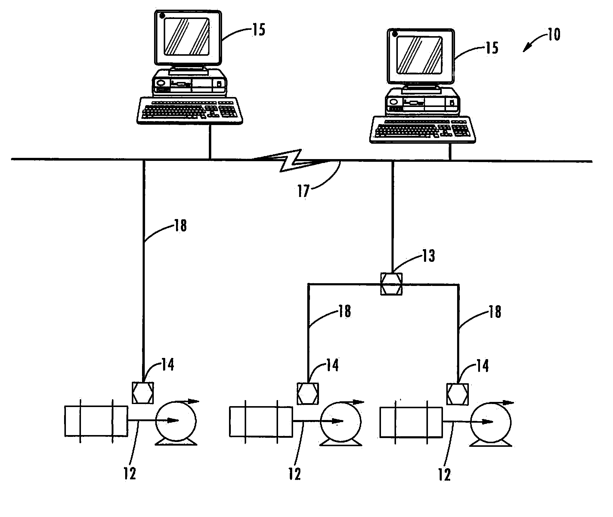
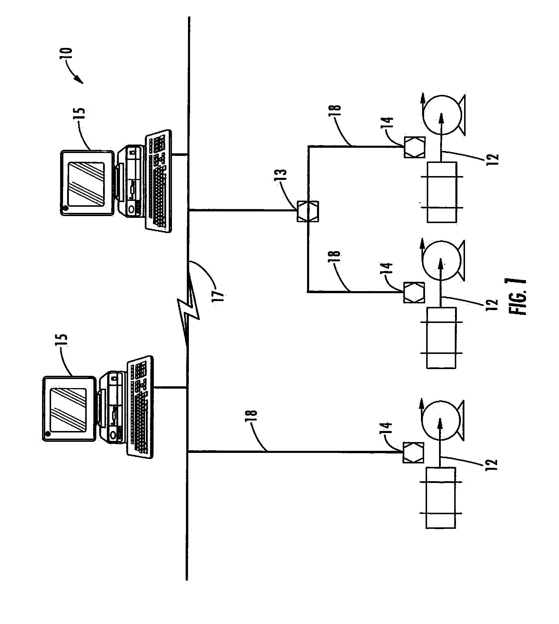
[0023]FIG. 1 depicts an exemplary machine condition monitoring system 10 constructed in accordance with certain aspects of the present invention is illustrated. In general, the exemplary machine condition monitoring system 10 is coupled to one or more machines 12. The system 10 comprises one or more condition reporting devices 14 coupled to a corresponding one of the machines 12. In the exemplary system of FIG. 1, each of the machines 12 is represented as a conventional AC induction motor directly coupled to a centrifugal pump, although the present invention is applicable to other machines such as fans, compressors, brushless DC machines, switched reluctance machines, and the like.

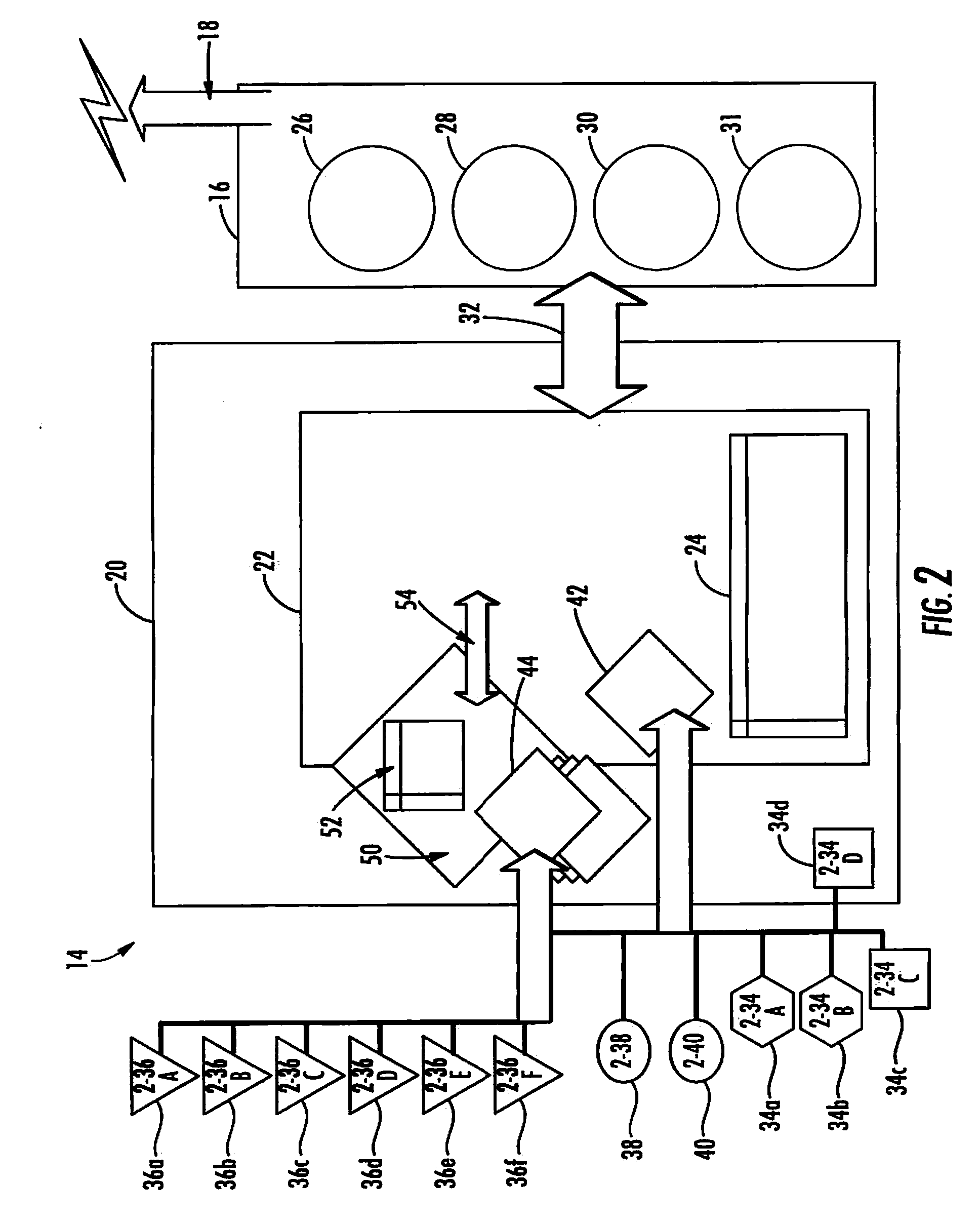
[0024] Each of the condition reporting devices 14 collects information concerning the operational status of the machine 12 with which it is associated. For example, each condition reporting device 14 may collect information concerning the vibrational characteristics of the machine 12, the temperature of t...


PUM


Abstract

A machine condition monitor resides in close proximity to a machine train, such as an AC inductive electric motor coupled to a driven unit such as a centrifugal pump or fan. A plurality of sensing devices are connected to the machine and the machine condition monitor. Machine state and condition parameters sensed by these devices are utilized by the machine condition monitor to derive machine condition values for each component and for the machine train as a whole. These derived condition values are transmitted via an industrial communications network to a control center where they can be trended and monitored. With no particular knowledge of machine analysis techniques or severity of specific machine faults, and no special training, Operators and Production Planners can use the condition values to plan production schedules, adjust process parameters, and request appropriate maintenance action.

Description

[0001] This application claims priority as a continuation application to U.S. patent application Ser. No. 11 / 047,268 filed Jan. 31, 2005 titled “Machine Condition Indication System,” the entire contents of which are incorporated herein by reference.FIELD OF THE INVENTION [0002] The present invention relates generally to systems and methods for categorizing the expected dependability (i.e., productive capability) of a machine asset. More particularly, the invention relates to a “Condition Transducer”—a sensing device for producing a value that is an analog of machinery condition in the same way a thermocouple produces a value that is an analog of temperature. BACKGROUND OF THE INVENTION [0003] Process operators, production planners, and maintenance personnel in industrial process environments must routinely make decisions about the utilization of their production assets. They want to know the productive capability of assets needed for successful completion of scheduled output. Operat...

Claims


Application Information

Patent Timeline
Patent Type & Authority Applications(United States)
IPC IPC(8): G08B21/00
CPCG05B19/4065G05B2219/32297G05B2219/31467G05B23/0232
Inventor BOUSE, KAIBOWERS, STEWART V. IIIROBINSON, JIMPIETY, RICHARDREEVES, TODD
Owner COMPUTATIONAL SYST
Why Eureka
Try Eureka