
Method for producing liquid-jet head and method for driving liquid-jet head

a liquid-jet head and production method technology, applied in metal-working equipment, printing, writing implements, etc., can solve the problems of inability to maintain predetermined sizes for large and small ink droplets, and achieve the effect of high-reliability printing

Inactive Publication Date: 2008-05-08
SEIKO EPSON CORP
View PDF5 Cites 16 Cited by
  • Summary
  • Abstract
  • Description
  • Claims
  • Application Information

AI Technical Summary

Benefits of technology

[0011] An advantage of some aspects of the invention is to provide a method for producing, and a method for driving, a liquid-jet head which can eject desired large and small liquid droplets, regardless of the individual error of the liquid-jet head.
[0015] According to this embodiment, in selecting the pulse signal for adjusting the size of the large dot, the pulse signal whose waveform corresponding to the vibration damping step has been adjusted in amplitude is used, whereby adjustment of the size can be made with ease.
[0017] According to this embodiment, when the waveform interval of the drive waveform is the integer n times the natural vibration cycle Tc of the liquid within the pressure generating chamber, the amplitude of the waveform corresponding to the vibration damping step is increased to enhance the vibration damping property. When the waveform interval of the drive waveform is (the integer n+½) times the natural vibration cycle Tc of the liquid within the pressure generating chamber, the amplitude of the waveform corresponding to the vibration damping step is decreased to enhance the vibration damping property. By this procedure, the large dot is controlled in a direction in which it becomes small. When adjustment is made in the reverse direction, the large dot is controlled in a direction in which it becomes large.
[0019] According to this embodiment, the interval between the ejection step and the vibration damping step is a half of the natural vibration cycle Tc of the liquid within the pressure generating chamber. Consequently, the vibration damping step acts effectively to damp vibration.
[0021] According to this embodiment, the second drive waveform and the second drive voltage can be selected from among those prepared beforehand. Thus, they can be set relatively easily.
[0024] According to the invention, the drive signal and the drive voltage can be set relatively easily so that desired large and small liquid droplets can be ejected, regardless of the individual error of the liquid-jet head. By driving the liquid-jet head using the drive signal and the drive voltage, highly reliable printing can be carried out.

Problems solved by technology

According to the above-described techniques, however, if variations in the capacity of supplying ink occur owing to the manufacturing error of the ink-jet recording head, particularly, the manufacturing error of an ink supply port for supplying ink to the reservoir, predetermined sizes may fail to be maintained for large and small ink droplets.

Method used


Image

  • Method for producing liquid-jet head and method for driving liquid-jet head
  • Method for producing liquid-jet head and method for driving liquid-jet head
  • Method for producing liquid-jet head and method for driving liquid-jet head

Examples


embodiment 1

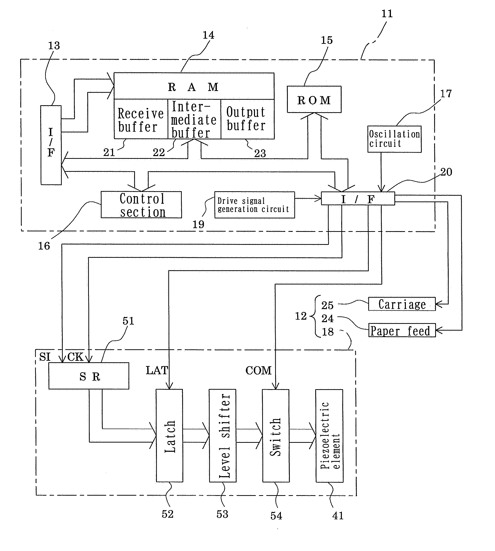
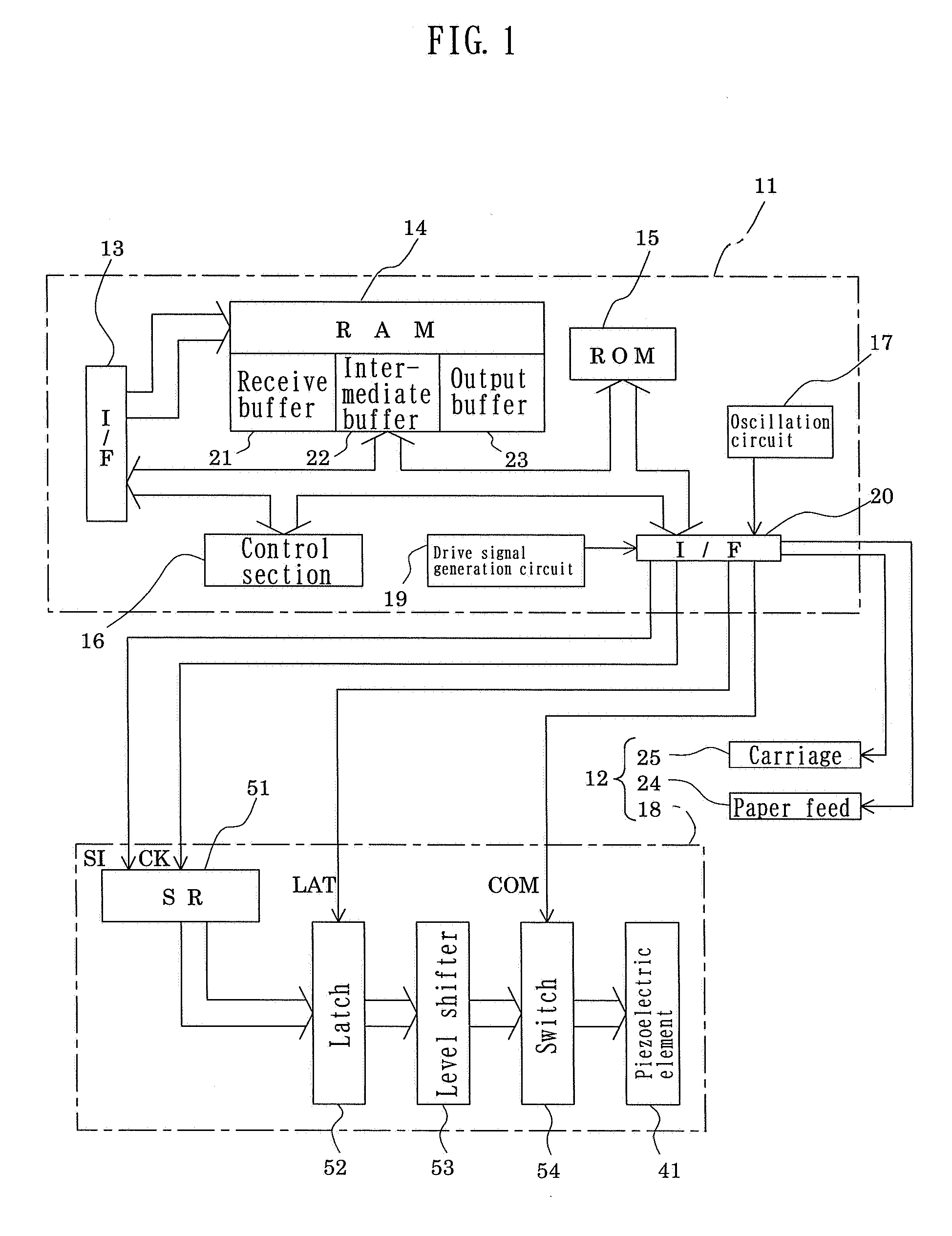
[0035]FIG. 1 is a view showing the schematic constitution of an ink-jet recording apparatus as an example of a liquid-jet apparatus to which Embodiment 1 of the invention is applied. As shown in FIG. 1, the ink-jet recording apparatus of the present embodiment is schematically composed of a printer controller 11 and a print engine 12.

[0036] The printer controller 11 comprises an external interface 13 (hereinafter referred to as external I / F 13), an RAM 14 for temporarily storing various data, an ROM 15 storing control programs, etc., a control section 16 configured to include a CPU, etc., an oscillation circuit 17 for generating a clock signal, a drive signal generation circuit 19 for generating a drive signal for supply to an ink-jet recording head 18, and an internal interface 20 (hereinafter referred to as internal I / F 20) for transmitting dot pattern data (bit map data), etc., expanded based on the drive signal or printing data, to the print engine 12.

[0037] The external I / F 1...

example 1

[0085] The present example shows a procedure for producing a liquid-jet head in which the natural vibration cycle of ink within the pressure generating chamber is 6.5 μsec; finally determining a drive signal (the above-mentioned second drive signal) and a drive voltage (the above-mentioned second drive voltage) for an individual head; and finalizing a liquid-jet head to be installed in an actual machine.

[0086] In the present example, as stated earlier, a drive signal having four pulse signals in one printing cycle is used, a standard drive voltage is 25V, a liquid droplet weighing 6 ng can normally be ejected by one pulse signal, a large dot weighs 24 ng upon selection of four pulse signals, a medium dot weighs 12 ng upon selection of two pulse signals, and a small dot weighs 6 ng upon selection of one pulse signal.

[0087] In the present example, for the sake of simplicity, a pulse signal having the waveform shown in FIG. 5 was used as the pulse signal. The durations of the steps b...

example 2

[0090] As in Example 1, the procedure shown in FIG. 7 was performed, and the results of measurement of the weight of the liquid droplet in each of the runs are shown in Table 2.

[0091] As shown in Table 2, when Rank 0 was set as a first drive signal and a drive voltage was set at 25V, the large dot weighed 24 ng as designed, but the medium dot weighed 13 ng, and the small dot weighed 6.5 ng, the values larger than the design values of 12 ng and 6 ng. Accordingly, Rank 2 was chosen as a second drive waveform, and a second drive voltage was set at 24V. As a result, the large dot weighed 24 ng, the medium dot weighed 12.4 ng, and the small dot weighed 6.2 ng, all the values falling within the design ranges. When the second drive signal was driven by the first drive voltage, the large dot measured was found to be 25.2 ng. Thus, it was confirmed that setting the drive signal at Rank 2 increased the size of the large dot.

TABLE 2DriveDriveLarge dotMedium dotSmall dotsignalvoltage(ng)(ng)...


PUM

PropertyMeasurementUnit
Massaaaaaaaaaa
Massaaaaaaaaaa
Massaaaaaaaaaa

Abstract

A liquid-jet head selectively forms a large dot or a small dot. The large dot is ejected when a plurality of pulse signals are selected, and the small dot upon selection of a smaller number of the pulse signals. There is a contraction of the pressure generating chamber to eject a droplet through the nozzle, and a vibration damping step. The drive waveforms are set to implement this approach, and have particular characteristics.

Description

[0001] The entire disclosure of Japanese Patent Application No. 2006-300744 filed Nov. 6, 2006 is expressly incorporated by reference herein. BACKGROUND [0002] 1. Technical Field [0003] The present invention relates to a method for producing, and a method for driving, a liquid-jet head in which a part of a pressure generating chamber communicating with a nozzle orifice for jetting a liquid is constructed of a vibration plate, a piezoelectric element is formed on the surface of the vibration plate, and the liquid is jetted by the displacement of the piezoelectric element. [0004] 2. Related Art [0005] Among liquid-jet apparatuses is, for example, an ink-jet recording apparatus having an ink-jet recording head comprising a plurality of pressure generating chambers for generating a pressure for ink droplet ejection by a piezoelectric element or a heat generating element, a common reservoir for supplying ink to each pressure generating chamber, and a nozzle orifice communicating with eac...

Claims


Application Information

Patent Timeline
IPC IPC(8): B41J29/38B23P17/00
CPCB41J2/0456B41J2/04581Y10T29/49401B41J2/04593B41J2/04596B41J2/04588
Inventor SAYAMA, TOMOHIRO
Owner SEIKO EPSON CORP
Learn More