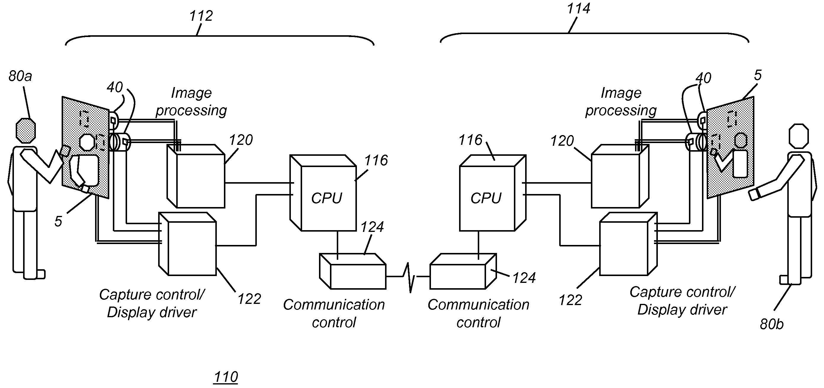
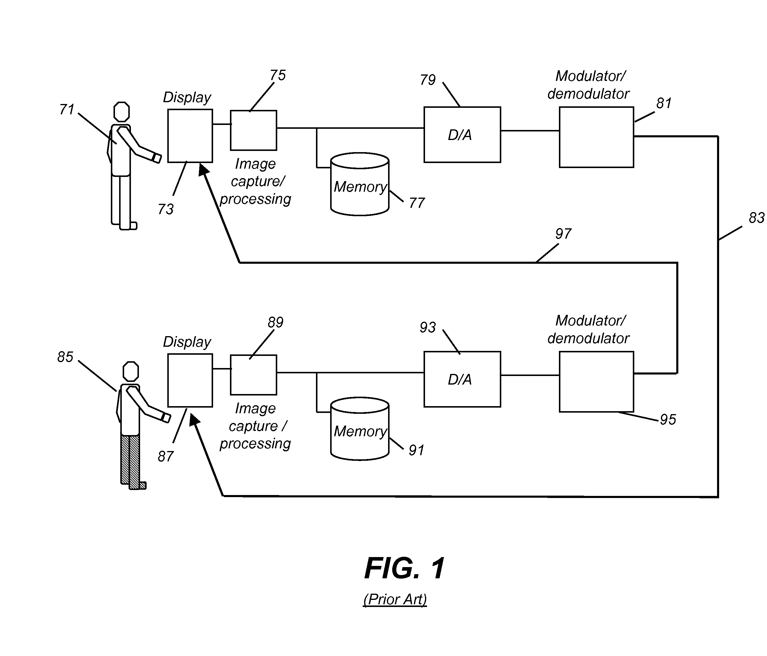
Although such systems have been produced and used for teleconferencing and other two-way communications applications, there are some significant practical drawbacks that have limited their effectiveness and widespread acceptance.
With conventional systems that follow the pattern of FIG. 1, poor eye contact results from locating the
video camera on a different
optical axis than the video monitor and causes the eyes of an observed participant to appear averted, which is undesirable for a
video communication system.
However, with many types of conventional imaging components, this can induce image
flicker and result in reduced display brightness.
Alternately transparent or semi-transparent
projection display screens can be difficult to construct and with rapid alternation between states, ambient contrast can suffer and
flicker can be perceptible.
As a number of these solutions show, this general approach can result in a relatively bulky apparatus that has a limited
field of view and is, therefore, difficult for the viewer to use comfortably.
Although this application describes pixel combinations for providing both image capture and display, however, the difficulty in obtaining
image quality with this type of a solution is significant and is not addressed in the Zanaty '0973 disclosure.
As an example of just one problem with this arrangement, the image capture pixels in the array are not provided with
optics capable of responding to changes in the scene such as movement.
Field of view and overall imaging performance (particularly resolution) are considerably compromised in these approaches.
The optical and computational task of piecing together a continuous image from numerous tiny images, each of which may exhibit considerable
distortion, is daunting, requiring highly complex and costly control circuitry.
In addition, imaging techniques using an array of imaging devices pointed in essentially the same direction tend to produce a series of images that are very similar in content so that it is not possible to significantly improve the overall
image quality over that of one of the tiny images.
Fabrication challenges, for forming multi-function pixels or intermingling image capture devices with display elements, are also considerable, indicating a likelihood of low yields, reduced resolution, reduced component lifetimes, and high manufacturing costs.
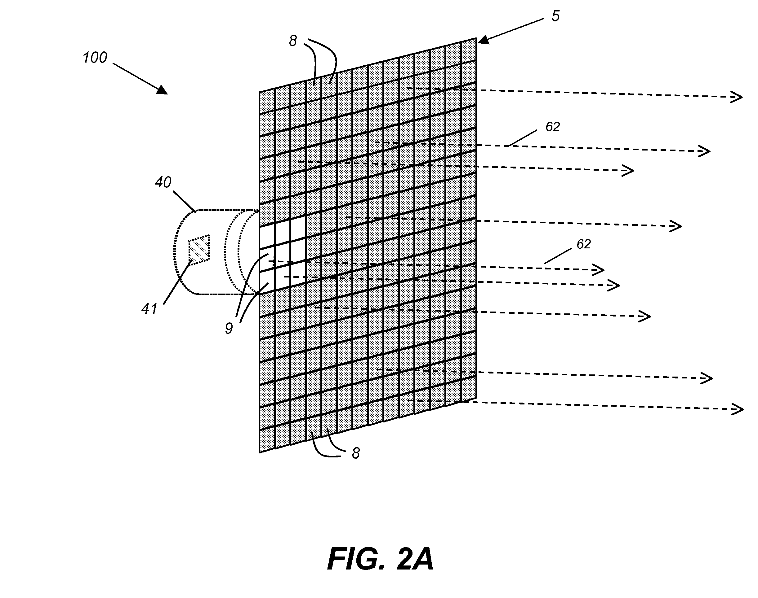
Images captured through a pinhole reflect low brightness levels and high
noise levels due to low
light transmission through the pinhole.
Undesirable “screen door” imaging anomalies can also occur with these approaches.
Display performance and brightness are also degraded due to the pinhole areas producing dark spots on the display.
As just indicated, a structure of integrated capture pixels intermingled in a display may cause artifacts for either the image capture
system or the
image display performance.
One difficulty with a number of conventional solutions relates to an inability to compensate for observer motion and changes in the
field of view.
Among approaches to this problem have been relatively complex systems for generating composite simulated images, such as that described in U.S.
Patent Application Publication No. 2004 / 0196360 entitled “Method and apparatus maintaining eye contact in
video delivery systems using view
morphing” by Hillis et al.
However, such approaches side-step the
imaging problem for integrated display and image capture devices by attempting to substitute synthesized
image content for true real-time imaging and thus do not meet the need for providing real-life interaction needed for more effective video-conferencing and communication.
The proliferation of solutions proposed for improved teleconferencing and other two-way video communication shows how complex the problem is and indicates that significant problems remain.

