Movable body drive system and movable body drive method, pattern formation apparatus and method, exposure apparatus and method, device manufacturing method, and decision-making method

Inactive Publication Date: 2008-05-08
NIKON CORP
View PDF99 Cites 143 Cited by
  • Summary
  • Abstract
  • Description
  • Claims
  • Application Information

AI Technical Summary

Benefits of technology

[0039] With this method, the movable body can accurately be driven in a measurement direction of the encoder system without being affected by the measurement error of the encoder system caused by (characteristics of) the head unit, and therefore the object held on the movable body can be exposed with high accuracy.
[0040] According to a fifteenth aspect of the present invention, there is provided a fifth exposure method in which an object is exposed with an energy beam, the method including: mounting the object on a movable body that can move in at least first and second directions that are orthogonal to each other within a predetermined plane; and driving the movable body within the predetermined plane, based on measurement information of an encod

Problems solved by technology

Meanwhile, as an apparatus other than the laser interferometer to be used for position measurement of a stage, an encoder can be cited, but because the encoder uses scales and the scales lack mechanical long-term stability (due to drift of scale pitch, fixed position drift, thermal expansion, and the like), and therefore, the encoder suffers from the disadvantages of lacking the linearity of the measurement values and being inferior in the long-term stability, compared with the laser interferometer.
However, for example, in the case the encoder is used for position measurement of a wafer stage within a moving plane in an exposure apparatus, even when the position of a stage on

Method used


Image

  • Movable body drive system and movable body drive method, pattern formation apparatus and method, exposure apparatus and method, device manufacturing method, and decision-making method
  • Movable body drive system and movable body drive method, pattern formation apparatus and method, exposure apparatus and method, device manufacturing method, and decision-making method
  • Movable body drive system and movable body drive method, pattern formation apparatus and method, exposure apparatus and method, device manufacturing method, and decision-making method

Examples


Embodiment Construction

[0078] An embodiment of the present invention will be described below, with reference to FIGS. 1 to 27.

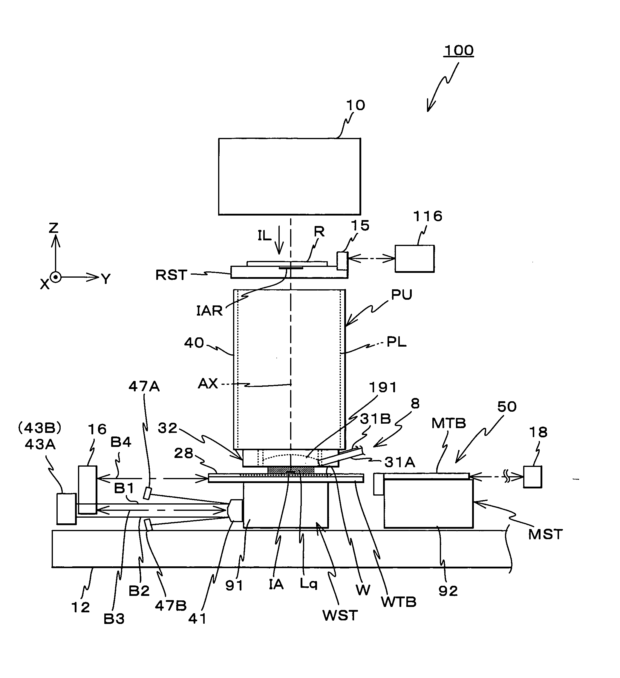
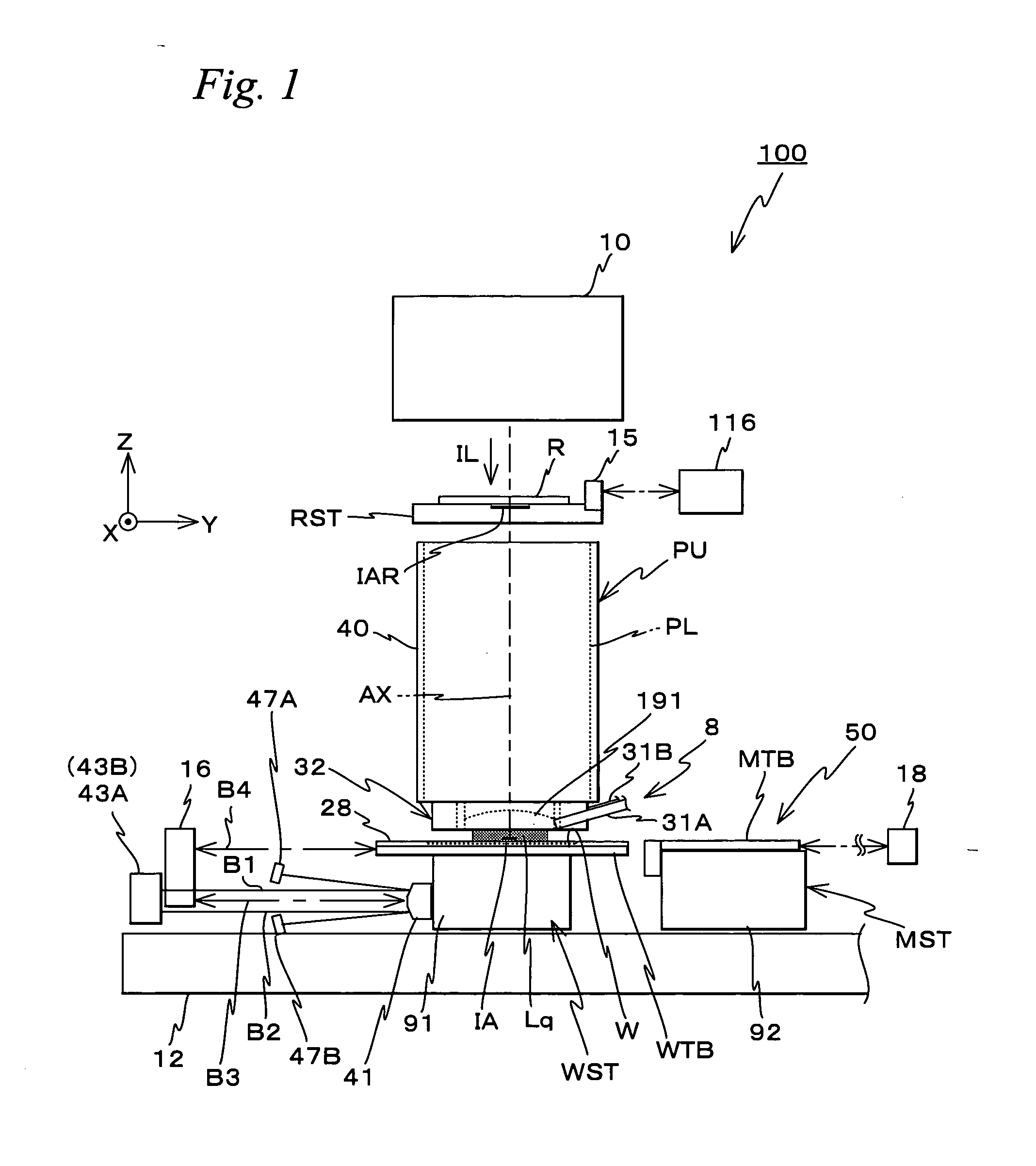
[0079]FIG. 1 schematically shows the configuration of an exposure apparatus 100 related to an embodiment. Exposure apparatus 100 is a scanning exposure apparatus by a step-and-scan method, that is, a so-called scanner. As will be described later, in the embodiment, a projection optical system PL is arranged, and the following description will be made assuming that a direction parallel to an optical axis AX of projection optical system PL is a Z-axis direction, a direction in which a reticle and a wafer are relatively scanned within a plane orthogonal to the Z-axis direction is a Y-axis direction and a direction that is orthogonal to a Z-axis and a Y-axis is an X-axis direction, and rotation (tilt) directions around the X-axis, the Y-axis and the Z-axis are ex, θy and θz directions respectively.

[0080] Exposure apparatus 100 includes an illumination system 10, a reticle stage RST t...


PUM


Abstract

A drive unit drives a wafer table in a Y-axis direction based on a measurement value of an encoder that measures position information of the wafer table in the Y-axis direction and based on known correction information in accordance with position information of the wafer table in a non-measurement direction (e.g. Z, θz and θx directions) that is measured by an interferometer at the time of the measurement by the encoder. That is, the wafer table (a movable body) is driven in the Y-axis direction based on the measurement value of the encoder that has been corrected by correction information for correcting a measurement error of the encoder that is caused by a relative displacement of a head and a scale in the non-measurement direction. Accordingly, the movable body can be driven with high accuracy in a desired direction while measuring the position by the encoder, without being affected by the relative motion between the head and the scale in directions other than a direction to be measured (measurement direction).

Description

CROSS-REFERENCE TO RELATED APPLICATIONS [0001] This non-provisional application claims the benefit of Provisional Application No. 60 / 853,750 filed Oct. 24, 2006, the disclosure of which is hereby incorporated herein by reference in its entirety.BACKGROUND OF THE INVENTION [0002] 1. Field of the Invention [0003] The present invention relates to movable body drive systems and movable body drive methods, pattern formation apparatuses and methods, exposure apparatuses and methods, device manufacturing methods, and decision-making methods, and more particularly to a movable body drive system and a movable body drive method that drive a movable body along a predetermined plane, a pattern formation apparatus equipped with the movable body drive system and a pattern formation method using the movable body drive method, an exposure apparatus equipped with the movable body drive system and an exposure method using the movable body drive method, a device manufacturing method using the pattern ...

Claims


Application Information

Patent Timeline
IPC IPC(8): G03B27/62G01V8/00
CPCG03F7/70775G03F7/70341G03F1/44G03F7/20G03F7/2041G03F7/70258G03F7/70275G03F7/70716G03F7/70758H01L21/0274H01L21/67727G03F7/70725G03F7/7085
Inventor SHIBAZAKI, YUICHI
Owner NIKON CORP
Why Eureka
Try Eureka