Light emitting module and light receiving module

a light emitting module and light receiving technology, applied in the field of light emitting modules and light receiving modules, can solve the problems of reducing the efficiency of light collecting, the brightness of light emitted from the lens b>12/b> is not optimal, and the light emitted from the light emitting module b>10/b> may not efficiently emit light, etc., to achieve the effect of reducing the brightness of an emitted light, enhancing efficiency, and minimizing

Inactive Publication Date: 2008-05-08
PANASONIC CORP
View PDF4 Cites 9 Cited by
  • Summary
  • Abstract
  • Description
  • Claims
  • Application Information

AI Technical Summary

Benefits of technology

[0014]Therefore, the first object of the present invention is to provide a light emitting module capable of reducing variations in brightness of an emitted light and enhancing efficiency while minimizing a diameter of a lens. Further, the second object of the present invention is to provide a light receiving module capable of enhancing light collecting efficiency while minimizing a diameter of a lens.
[0023]Preferably, the plurality of second refraction surfaces have such a shape as to remove, from the emission surface of the lens element, an invalid portion for preventing emission of an emission light emitted by the light source.
[0032]Preferably, the plurality of second refraction surfaces have such a shape as to remove, from the incident surface of the lens element, an invalid portion for preventing the incident light from being collected on the light receiving element.
[0033]As described above, the light emitting module according to the present invention allows reduction of variations in brightness of an emitted light, and enhancement of efficiency while minimizing the diameter of the lens. Further, the light receiving module according to the present invention allows enhancement of light collection efficiency while minimizing the diameter of the lens.

Problems solved by technology

However, due to, for example, limitations in processing the plurality of refraction surfaces 3 so as to make inclination angles thereof, the Fresnel lens is configured such that a reception angle 2β at which a light emitted from the light source 1 is received has only a limited value.
Therefore, when an angle at which the light source 1 emits a light is large, the light emitting module 10 may not efficiently emit the light.
Therefore, the light emitting module 11 has a problem that a light emitted from the lens 12 has variations in brightness.
Therefore, the light receiving module 20 has a problem that light collecting efficiency is reduced due to an area in which no incident light is collected.

Method used


Image

  • Light emitting module and light receiving module
  • Light emitting module and light receiving module
  • Light emitting module and light receiving module

Examples


first embodiment

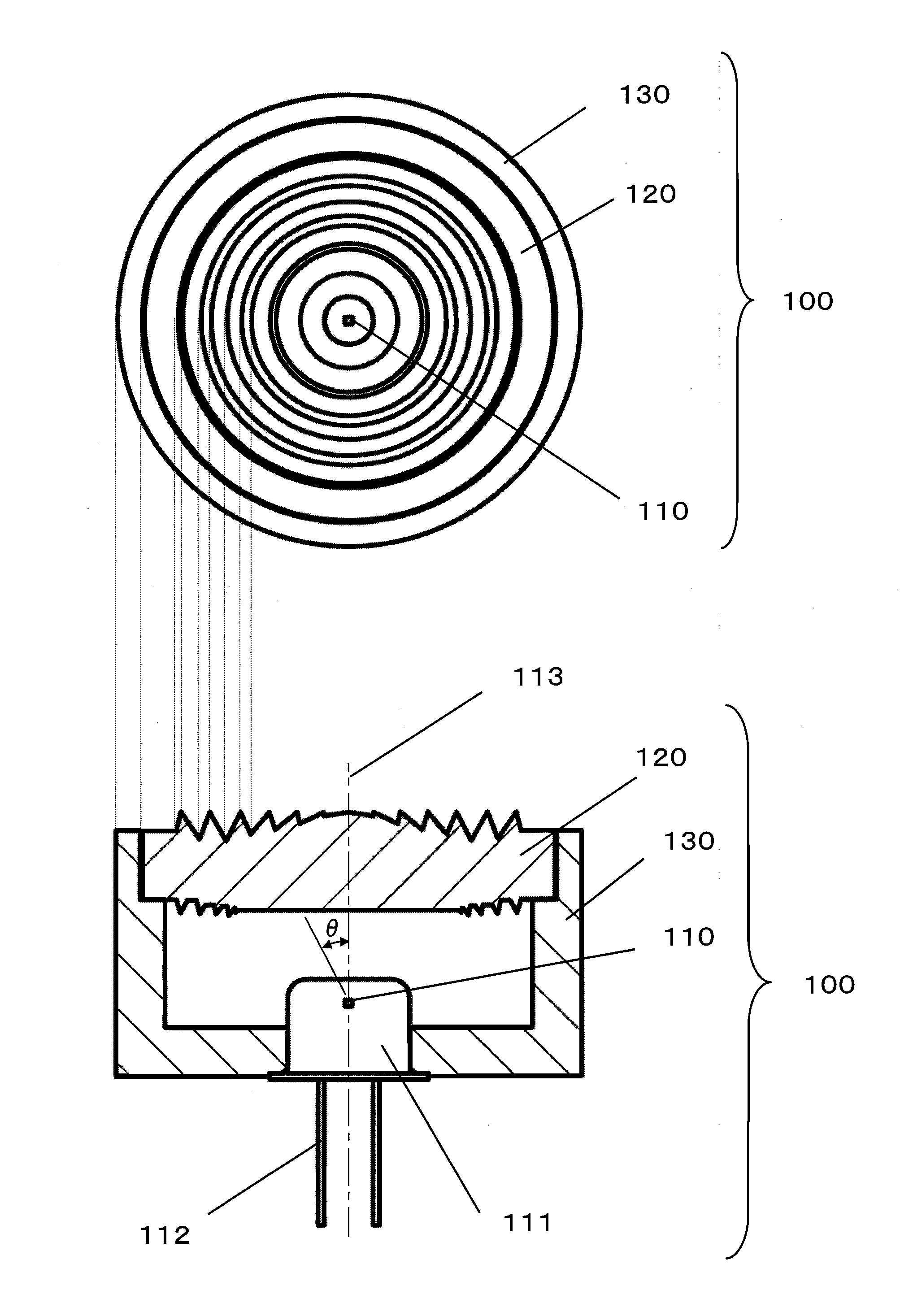
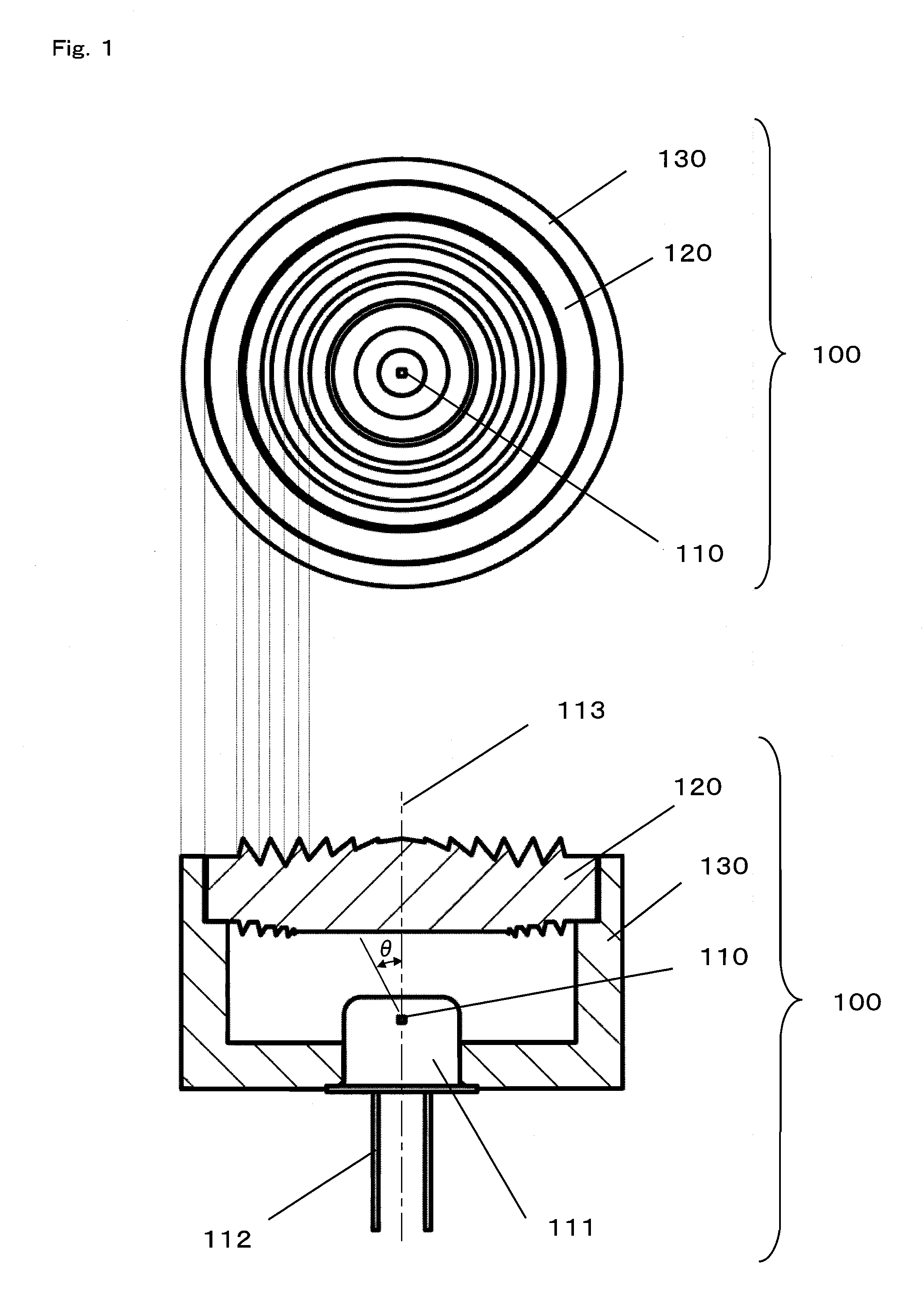
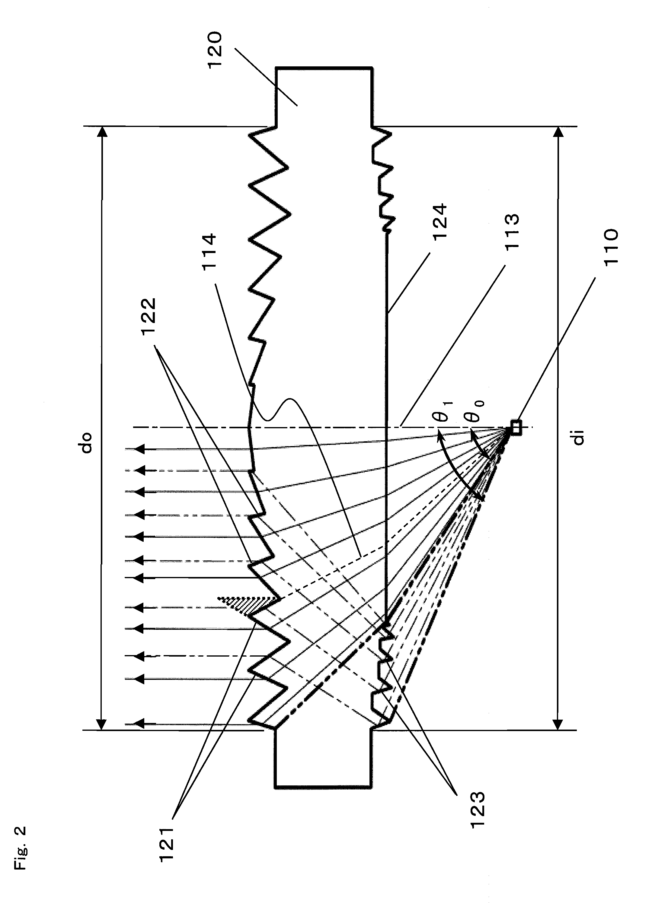
[0067]FIG. 1 is a top view and a side cross-sectional view of a light emitting module 100 according to a first embodiment of the present invention. FIG. 2 is a side cross-sectional view of a principal portion of the light emitting module 100 according to the first embodiment of the present invention.

[0068]As shown in FIG. 1 and FIG. 2, the light emitting module 100 mainly comprises a light source 110 and a lens element 120. As the light source 110, for example, a LED or a semiconductor laser is used. The light source 110 is accommodated in a package 111. The package 111 and the lens element 120 are fixed, in a housing 130, at such positions as to satisfy a predetermined positional relationship therebetween. A modulated electrical signal is supplied to the light source 110 through a terminal 112, and the light source 110 emits a light signal having, for example, its light emission intensity varied in accordance with the modulated signal, so as to spread out the light signal from an o...

second embodiment

[0092]In the first embodiment, a light emitted from the light source at an emission angle, ranging from θ0 to θ1, representing an angle between the optical axis and the emission direction is utilized so as to reduce variations in brightness of an emitted light, thereby realizing the light emitting module enabling highly efficient performance. According to the second embodiment, a light which is emitted from the light source but does not directly reach the lens element is utilized instead of the light emitted from the light source at the emission angle, ranging from θ0 to θ1, representing the angle between the optical axis and the emission direction.

[0093]FIG. 10 is a top view of a light emitting module 600 according to a second embodiment of the present invention, and FIG. 11 is a side cross-sectional view of the light emitting module 600 according to the second embodiment of the present invention. FIG. 12 is a side cross-sectional view of a principal portion of the light emitting m...

third embodiment

[0103]FIG. 19 is a top view and a side cross-sectional view of a light receiving module 2100 according to a third embodiment of the present invention. FIG. 20 is a side cross-sectional view of a principal portion of the light receiving module 2100 according to the third embodiment of the present invention.

[0104]As shown in FIG. 19 and FIG. 20, the light receiving module 2100 mainly comprises a light receiving element 2110 and a lens element 2120. As the light receiving element 2110, for example, a photodiode (PD) is used. The light receiving element 2110 is accommodated in a package 2111. The package 2111 and the lens element 2120 are fixed, in a housing 2130, at such positions as to satisfy a predetermined positional relationship therebetween. The light receiving module 2100 receives a light signal (for example, a light signal emitted from the light emitting module 100 of the first embodiment) from an optical wireless transmitter (not shown) provided so as to face the light receivi...


PUM


Abstract

A plurality of first refraction surfaces 121 and a plurality of second refraction surfaces 122 are alternately provided on an emission surface of a lens element 120 so as to form concentric circles each having an optical axis 113 at the center thereof, and having diameters different from each other, and a light reflected by a plurality of reflection surfaces 123 provided on an incident surface of the lens element so as to form concentric circuits each having the optical axis 113 at the center thereof and having diameters different from each other, is refracted and emitted by the plurality of second refraction surfaces 122 at desired angles. Therefore, it is possible to enhance efficiency and an emission intensity, and reduce variations in brightness of an emitted light without increasing the diameter of the lens element 120, thereby realizing a light emitting module 100 enabling advantageous performance.

Description

BACKGROUND OF THE INVENTION[0001]1. Field of the Invention[0002]The present invention relates to a light emitting module and a light receiving module for use in, for example, an optical wireless transmitter and an optical wireless receiver, respectively, of an optical wireless transmission system for transmitting information data such as a video signal, an audio signal, and a digital data signal, as an optical signal through a free space, and more particularly to a light emitting module which allows reduction of variations in brightness of an emitted light and enhancement of efficiency, and a light receiving module having enhanced light collection efficiency.[0003]2. Description of the Background Art[0004]An optical wireless transmission system for transmitting an optical signal through a free space has advantageous characteristics that transmission can be performed at a higher speed than radio transmission using a radio wave because a light enables a broadband transmission. In orde...

Claims


Application Information

Patent Timeline
Patent Type & Authority Applications(United States)
IPC IPC(8): G02B3/02
CPCG02B3/08
Inventor IEDA, TOMOAKISASAI, HIROYUKI
Owner PANASONIC CORP
Why Eureka
Try Eureka