Method and apparatus for biometric identification

a biometric identification and method technology, applied in the field of biometric identification of individuals, can solve the problems of loss of measurement accuracy, false acceptance, and sensors which must be touched by everyone accessing a public facility, and achieve the effects of reducing false rejection rate, low cost, and eliminating measurement errors caused by uncertainties in target range and horizontal registration

Inactive Publication Date: 2008-05-08
CERNI CONSULTING
View PDF11 Cites 103 Cited by
  • Summary
  • Abstract
  • Description
  • Claims
  • Application Information

AI Technical Summary

Benefits of technology

[0015]The present invention solves the problem described above and advances the art by providing an innovative, low cost, electro-optical method and apparatus, with no moving parts, yielding the first truly non-contact hand vein biometric sensor, wherein measurement errors caused by uncertainties in the target range and horizontal registration have been eliminated. In the preferred embodiment, the additional electro-optical components which must be added to the infrared imager module consist of a low power laser diode, a collimating lens or mirror, and laser driver circuitry, the sum of which costs approximately ten dollars, for high volume applications. Preferably, the target is a palm, back or a hand, or finger. Preferably, a single laser diode (LD) illuminates the target in such a way that the pattern of reflected radiation, when viewed by a conventional vein pattern infrared imager, provides a di...

Problems solved by technology

Conversely, it has been shown that a clay model of a fingerprint can fool a fingerprint scanner, yielding a false acceptance.
In some cultures, sensors which must be touched by everyone accessing a public facility is considered highly undesirable.
Furthermore, contact sensors which must be touched by everyone accessing a public facility accumulate dirt, resulting in a loss of measurement accuracy.
If Asia were to suffer a major outbreak of lethal bird flu or similar contagious disease, it could wreak havoc on biometric identification systems based upon contact sensors.
The largest technical challenge which one faces when attempting to design a non-contact vein pattern biometric sensor is that of focusing the target (hand) onto the infrared imager in lieu of the fact that all such biometric infrared imagers have a fixed focus.
This would result in a recorded image which is out-of-focus, such that one would be unable to read some or all of the words on this page.
For the vein pattern biometric sensor, an out-of-focus image will result in a vein pattern which is unrecognizable, such that all individuals scanned would be rejected by the biometric identification system.
Those components by themselves are incapable of providing data from which target range can be accurately determined.
One could attempt to add an autofocus lens to a vein pattern biometric sensor similar to that included in most digital camera systems; however, that would create multiple, additional problems: (a) It is very difficult for conventional, inexpensive autofocus lens systems to provide sharply focused images at the very short target ranges (about 50 mm) and wide field of view required of a biometric imagers; (b) a high quality autofocus lens suitable for biometric applications adds significant cost to the sensor, and (c) mechanical components of inexpensive autofocus systems would wear out with the frequent use required of typical biometric sensors, such as thousands of uses per week 52 weeks per year.
However, neither...

Method used


Image

  • Method and apparatus for biometric identification
  • Method and apparatus for biometric identification
  • Method and apparatus for biometric identification

Examples


Embodiment Construction

1. Preferred Embodiment for Palm Vein Pattern Identification

[0029]This detailed description of the preferred embodiment describes an electro-optical system and method for improved performance of subcutaneous vein pattern imagers for biometric identification, preferably hand vein imagers, and still more preferably palm vein imagers. Those skilled in the art can easily adapt the electro-optical devices described in this section to subcutaneous vein pattern imagers designed to scan other parts of the human body. Hand vein imagers include imagers that image the veins in any portion of the hand, including the palm of the hand, the back of the hand, or the front or back of any of the fingers.

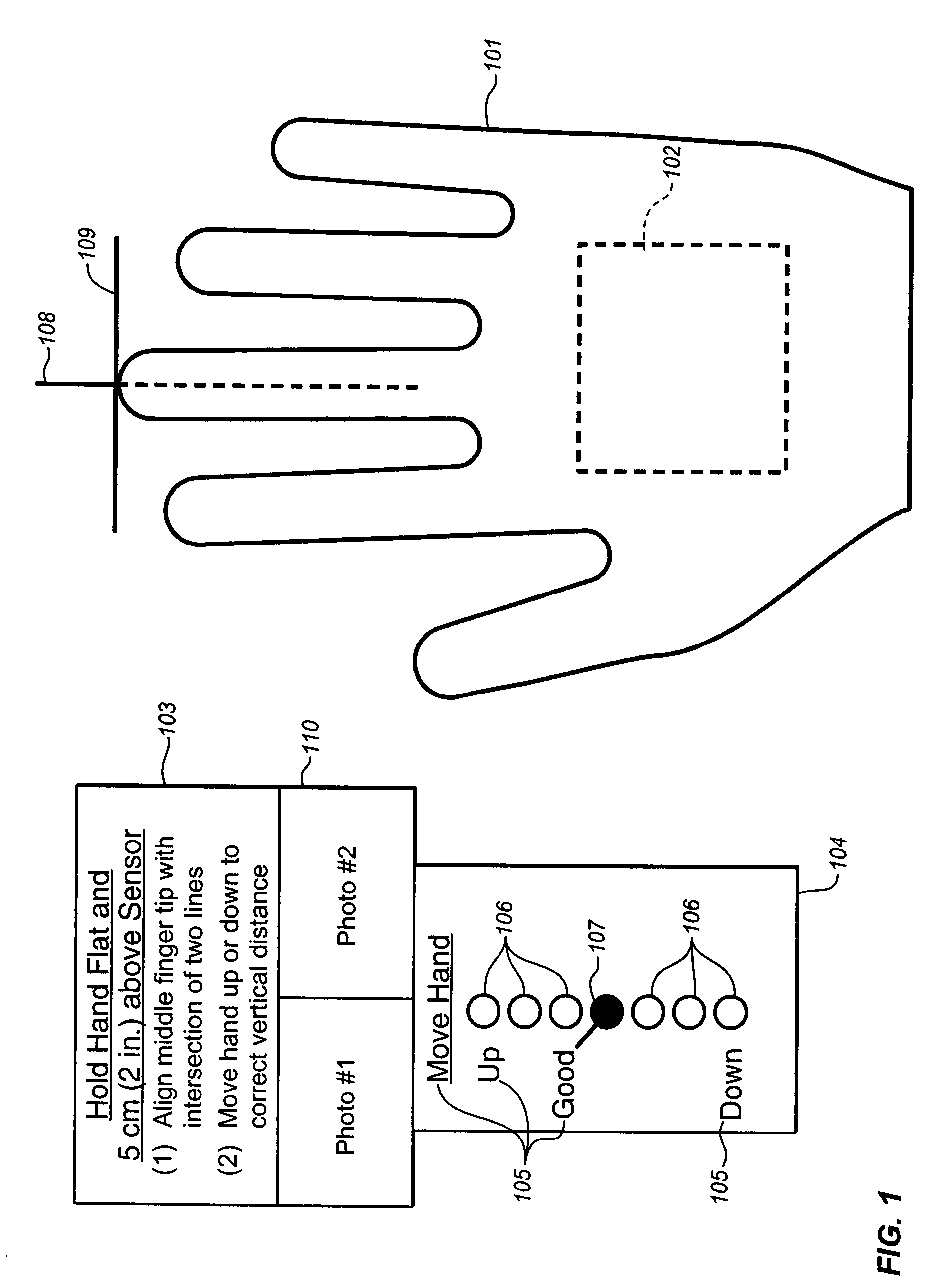
[0030]FIG. 1 depicts how the biometric identification system appears to the individual being scanned; it shows a view looking down on the back of the right hand 101. The infrared imager module 102 is beneath the hand and, therefore, is depicted by the dashed lines. To the left of the hand is an instru...


PUM


Abstract

The invention describes the first practical, cost effective, truly non-contact implementation of a subcutaneous vein pattern biometric sensor. A laser diode (LD) illuminates the hand in such a way that the pattern of reflected radiation, when viewed by a conventional vein pattern infrared imager, provides a direct measure of target range. Said target range measurement is used to create a visual or audio signal that instructs the individual being scanned to place the hand at precisely the optimum range, such that the vein pattern is in focus. Furthermore, a system and apparatus are described to direct the individual being scanned to move the hand to an optimal horizontal registration or position with respect to the infrared imager.

Description

CROSS-REFERENCE TO RELATED APPLICATIONS[0001]This Application is a Non-Provisional of Provisional (35 USC 119(e)) Application No. 60 / 856,576 filed on Nov. 3, 2006.FIELD OF THE INVENTION[0002]The invention pertains to biometric identification of individuals using subcutaneous vein pattern recognition, through infrared imaging of a portion of the body, most typically a portion of the hand.BACKGROUND OF THE INVENTION[0003]Biometric identification of individuals represents a small but rapidly growing commercial market. It has been estimated that the market for biometric sensors and systems will reach $4 billion by 2008. Motivations for increased use of biometric identification include any anti-terrorist screening, such as screening of airline passengers and access control at government and commercial facilities, plus protection against identity theft caused by theft of financial account numbers and passwords. Regarding the latter, some major banks have installed biometric identification...

Claims


Application Information

Patent Timeline
IPC IPC(8): G06K9/00
CPCG06K9/00033G06K2009/00932G06K9/036G06K9/00912G06V40/1312G06V40/67G06V40/14G06V10/993
Inventor CERNI, TODD A.
Owner CERNI CONSULTING
Why Eureka
Try Eureka