Developing roller, manufacturing method thereof, developing apparatus and image forming apparatus

a technology of developing rollers and manufacturing methods, applied in electrographic processes, instruments, roads, etc., can solve the problems of low yield, insufficient charging and fog, etc., and achieve the effect of high reliability

Inactive Publication Date: 2008-05-08
SEIKO EPSON CORP
View PDF31 Cites 13 Cited by
  • Summary
  • Abstract
  • Description
  • Claims
  • Application Information

AI Technical Summary

Benefits of technology

[0014]Advantages of the invention are to provide a developing roller and a manufacturing method thereof that prevent insufficient charging of toner and require less toner consumption caused by fog and to provide a developing apparatus including this developing roller, and an image forming apparatus including this developing apparatus.

Problems solved by technology

Therefore, there is a problem in that the deformation of the cylindrical material occurs because of the use of abrasive grains, resulting in low yield.
However, because the grinding marks (unevenness) of this developing roller are formed along the rotation direction of the roller, if toner is to be charged by friction, a developer rolls along the rotational direction of the roller to thereby make small the frictional resistance due to unevenness.
As a result, the developing roller causes insufficient charging and fog to occur.

Method used


Image

  • Developing roller, manufacturing method thereof, developing apparatus and image forming apparatus
  • Developing roller, manufacturing method thereof, developing apparatus and image forming apparatus
  • Developing roller, manufacturing method thereof, developing apparatus and image forming apparatus

Examples


first embodiment

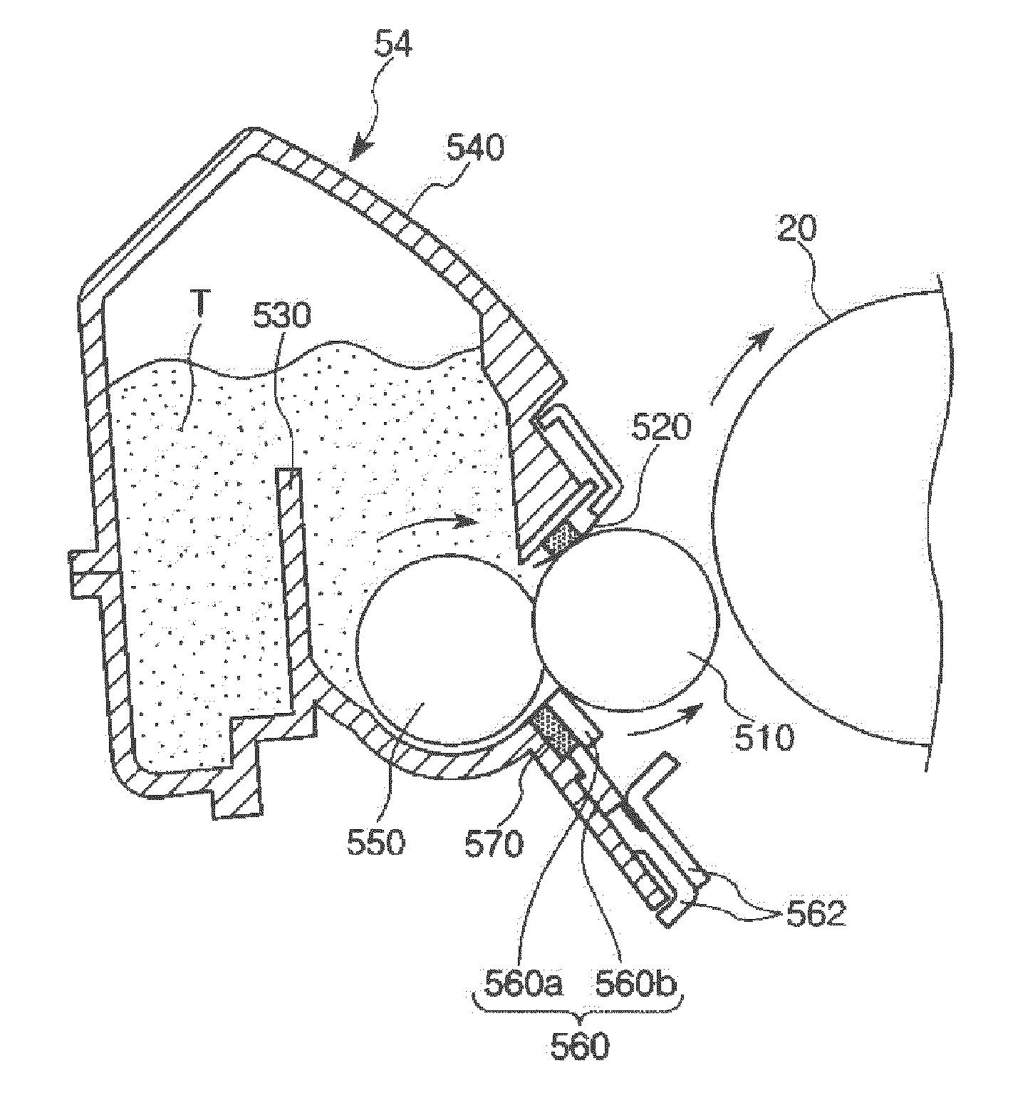
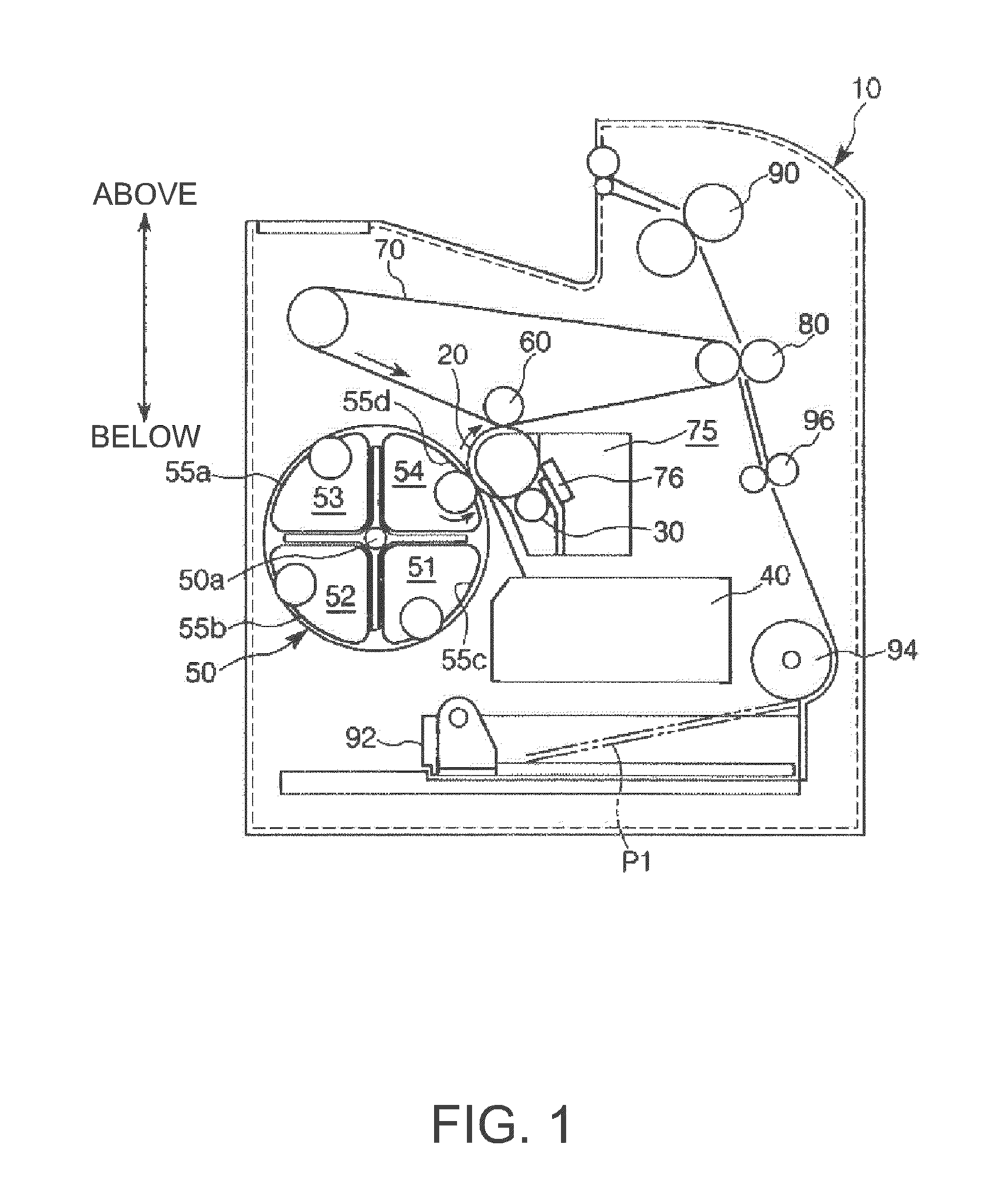
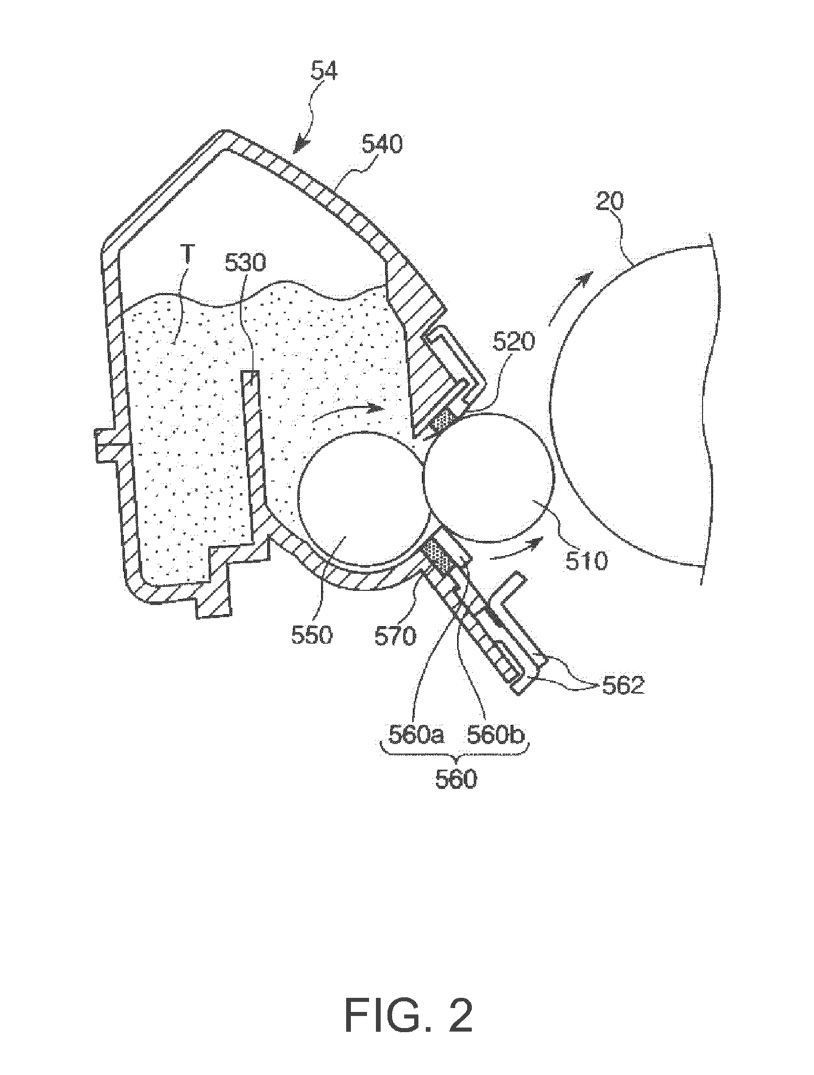
[0064]FIG. 1 is a schematic sectional view showing a schematic structure of an image forming apparatus in accordance with the invention, and FIG. 2 is a schematic sectional view showing a schematic structure of a developing apparatus in accordance with (a first embodiment of) the invention.

[0065]Note that hereinafter the upper side and the lower side in the figures will be referred to as “above” and “below”, respectively.

[0066]Image Forming Apparatus

[0067]Referring to FIG. 1, a laser-beam printer (hereinafter referred to only as a “printer”) 10 as an example of an image forming apparatus will be described.

[0068]As shown in FIG. 1, the printer 10 has a photosensitive member 20 that carries a latent image and rotates in the arrow direction in the figure.

[0069]Disposed along the rotation direction (clockwise) of the photosensitive member 20 are a charging unit 30, an exposure unit 40, a developing unit 50, a primary transfer unit 60 and an intermediate transfer member 70, and a cleanin...

second embodiment

[0403]FIG. 9 is an enlarged plan view of the groove 2 formed in the developing roller 510.

[0404]A second embodiment of the developing roller 510 of the invention will be described below with reference to this drawing.

[0405]Description will be given mainly on differences from the above embodiment, and explanation on the same elements as those of the above embodiment will be omitted.

[0406]This embodiment differs from the first embodiment in the shape of the protrusion portion 3 and the crossing angle between the first groove 21 and the second groove 22.

[0407]As shown in FIG. 9, the top surface 31 of the protrusion portion 3 is of a approximately planar, rhombic shape.

[0408]That is, the plurality of first grooves 21 and the plurality of second grooves 22 intersect each other, but do not intersect at right angles.

[0409]The angle θ in this case at which the first groove 21 and the second groove 22 intersect each other is preferably 20 to 135°, and more preferably 45 to 90°.

[0410]Setting ...

third embodiment

[0416]FIG. 10 is a plan view showing a schematic structure of the developing roller 510.

[0417]A third embodiment of the developing roller 510 of the invention will be described below with reference to this drawing.

[0418]Description will be given mainly on differences from the above embodiments, and explanation on the same elements as those of the above embodiments will be omitted.

[0419]This embodiment is the same as the first embodiment except that the surface roughness Ro of the top surfaces 31 of the protrusion portions 3 partially varies along the longitudinal direction of the main body 300.

[0420]In other words, while the surface roughness RO of the top surface 31 of the protrusion portion 3 is the same for the whole of the groove formation section 320 in the first embodiment, the surface roughness RO of the top surface 31 located at an end portion 323 of the groove formation section 320 of the main body 300 is smaller than that of the top surface 31 located at a center portion 3...


PUM

PropertyMeasurementUnit
angleaaaaaaaaaa
diameteraaaaaaaaaa
diameteraaaaaaaaaa

Abstract

A developing roller on a circumferential surface of which toner is held includes a plurality of first grooves formed in parallel to each other at approximately equal intervals, each in a direction inclined to a circumferential direction of the circumferential surface of the developing roller; a plurality of second grooves formed in parallel to each other at approximately equal intervals, each in a direction inclined to the circumferential direction of the circumferential surface of the developing roller, each second groove intersecting each first groove, the first groove and the second groove each having a U-shaped cross section; and a protrusion portion disposed in an area surrounded by the first groove and the second groove. In the developing roller, the protrusion portion has on a top surface thereof a plurality of minute projections, and when a surface roughness Rz of the top surface is RO, RO is 0.5 to 2 times an average grain size of a particle of the toner; when a distance from an average line of a roughness curve of the surface roughness RO to a deepest part of the first groove is D1 and a distance from the average line of the roughness curve of the surface roughness RO to a deepest part of the second groove is D2, each of D1 and D2 is 0.5 to 2 times the average grain size of the particle of the toner; and a relationship of the RO<D1 and the RO<D2 is satisfied.

Description

BACKGROUND OF THE INVENTION[0001]1. Technical Field[0002]The present invention relates to a developing roller, a manufacturing method thereof, a developing apparatus and an image forming apparatus.[0003]2. Related Art[0004]Image forming apparatus that adopt electrophotography, such as copiers and printers, form images of toner on paper and other recording media by a series of image forming processes including a charging process, an exposure process, a developing process, a transfer process and a fixing process.[0005]For example, in a developing process, with a developing roller that carries toner brought into contact with a photosensitive member that carries an electrostatic latent image, charged toner is provided from the developing roller to the latent image to visualize the latent image as a toner image.[0006]For example, a developing roller for single component development as described in JP-A-55-26526 has hitherto been known as a roller for providing (applying) powder such as t...

Claims


Application Information

Patent Timeline
Patent Type & Authority Applications(United States)
IPC IPC(8): G03G15/08
CPCG03G2215/0177G03G15/0818
Inventor SUZUKI, JUNICHISAKURAI, NOBORU
Owner SEIKO EPSON CORP
Why Eureka
Try Eureka