Flow cytometers

a flow cytometer and flow cytometer technology, applied in the field of flow cytometers, can solve the problems of difficult displacement of pmts with other detectors, inability to compare test results from different instruments, and inability to compare results from one day to the next, etc., and achieve the effect of reliable comparison

Active Publication Date: 2008-05-08
GENETIX LTD
View PDF7 Cites 39 Cited by
  • Summary
  • Abstract
  • Description
  • Claims
  • Application Information

AI Technical Summary

Benefits of technology

[0020]The calibration process of the invention allows the results from the different flow cells to be reliably compared. In turn this allows a flow cytometer to be provided according to the invention that comprises a plurality of measurement units arranged along a common flow path through which a sample to be studied flows, thereby flowing passed each measurement unit in turn, wherein each measurement unit comprises a flow cell, and wherein each flow cell is arranged in optical communication with a fluorescence detection assembly comprising a spectral sorting arrangement for separating fluorescence extending over a wavelength range into a plurality of at least four wavelength bands, and a single detector module with a plurality of channels to which the spectral sorting arrangement is optically coupled so that respective channels thereof receive respective ones of the wavelength bands.

Problems solved by technology

Otherwise, for example, test results from different instruments cannot be compared and results from one day to the next cannot be compared.
However, PMTs are difficult to displace with other detectors in view of their extremely high sensitivity.

Method used


Image

  • Flow cytometers
  • Flow cytometers
  • Flow cytometers

Examples


Embodiment Construction

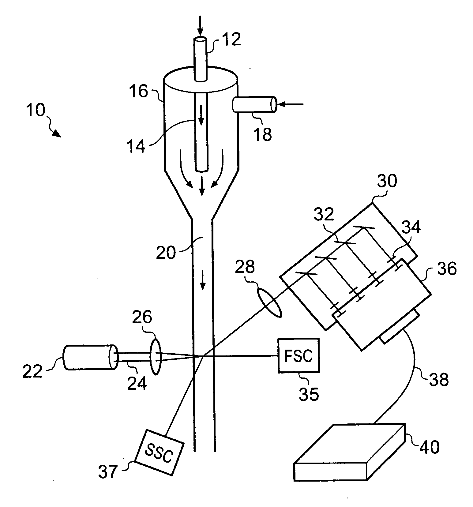
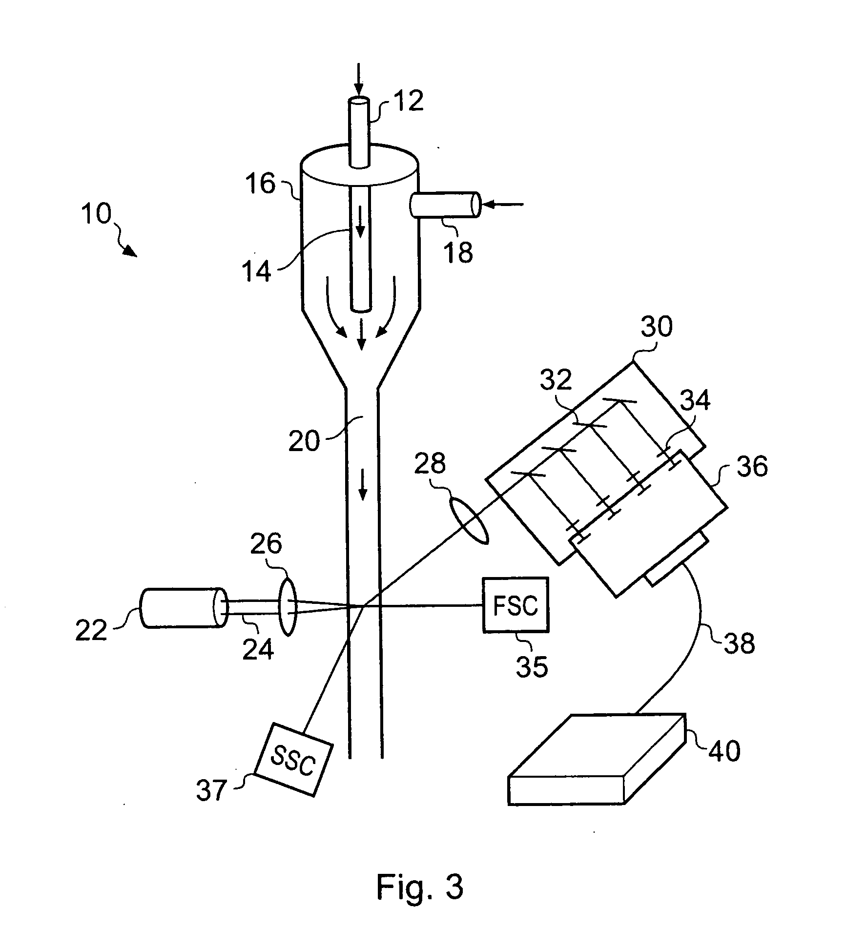
[0032]FIG. 3 shows schematically the flow cell region of a flow cytometer embodying the invention. The apparatus is similar in many respects to the prior art apparatus shown in FIG. 1 and the same reference numerals are used for corresponding parts.

[0033]Namely, the flow cytometer has a flow cell 10 which receives a sample inlet tube 12. The sample inlet tube 12 is connected to an inner capillary tube 14 of the flow cell 10 which is radially enclosed prior to its termination by a sheath 16 which has a sheath inlet 18 connected to a sheath fluid inlet tube (not shown). As considered in the flow direction, the sheath 16 reduces in its cross-sectional diameter and the inner capillary tube 14 terminates leaving the sample fluid and sheath fluid flowing together along a capillary tube 20. After this termination, the sample flows radially confined to the central region of the flow through laminar flow being preserved at the interface between the sample fluid and the sheath fluid. The aim ...


PUM

PropertyMeasurementUnit
wavelengthsaaaaaaaaaa

Abstract

A calibration method for a flow cytometer with a multichannel detector module. During calibration, the fluorescence intensity data values for the different detector channels are used to calculate normalization factors needed to adjust subsequent data collected by each of the channels. By using a multichannel detector module, the results from the different flow cells can be reliably compared, so that multiple stages of flow cells can be arranged in series along a common flow path, for example to measure the same sample at defined time intervals.

Description

BACKGROUND OF THE INVENTION[0001]The invention relates to flow cytometers and to methods of calibrating and using flow cytometers.[0002]Flow cytometers are widely used for analysing properties of cells that are suspended in a liquid. The liquid is passed through a conduit so that the cells flow past a fluorescence-based sensing device one at a time. The cells can thus be counted and classified according to their spectroscopic properties which can then optionally be used to further direct the flow or for other purposes. For example, the cells can be sorted downstream of the detection device according to their fluorescence properties. This is usually referred to as fluorescence activated cell sorting (FACS).[0003]The instrument typically is provided with multiple detectors to collect both forward and side scattered light from the cells. Side scatter (SSC) refers to an orthogonal, or at least transverse, alignment of the optical axes of the excitation and-collection optics. Forward sca...

Claims


Application Information

Patent Timeline
Patent Type & Authority Applications(United States)
IPC IPC(8): G01N21/64
CPCG01N15/1012G01N2015/1409Y10T436/10Y10T436/2575G01N2015/1415
Inventor JIANG, YONGGANG
Owner GENETIX LTD
Why Eureka
Try Eureka