Magnetic resonance apparatus and method for prospective motion correction

a magnetic resonance and motion correction technology, applied in the field of magnetic resonance imaging, can solve the problems of reducing the mr image quality, motion artifacts, and purely retrospective techniques suffering from inherently limited motion correction accuracy, and achieve the effect of reducing the bold contrast distortion interaction between spatially adjacent slices and long-term stability

Active Publication Date: 2018-10-02
SIEMENS HEALTHCARE GMBH
View PDF3 Cites 1 Cited by
  • Summary
  • Abstract
  • Description
  • Claims
  • Application Information

AI Technical Summary

Benefits of technology

[0017]The inventive method is based on the insight that, for determining the motion correction parameters, the region of interest should not be regarded as a whole, but rather split or divided into individual blocks, i.e. the aforementioned sub-regions. As a result, movements taking place on a short timescale compared to the scan time of the complete MR image can also be taken into account relatively precisely. This is achieved by the scan time being subdivided for acquiring the first MR data and the second MR data, respectively. It is not necessary for the entire region of interest to consist of a disjunctive combination of the individual sub-regions. Advantageously, individual sub-regions can overlap, thereby increasing the robustness of the method. For example, sub-regions for which MR data are acquired in a time-sequential manner can overlap.
[0046]In addition, it is possible to determine the motion correction parameters particularly precisely. The slices of the first MR data in the interleaved acquisition scenario are spaced farther apart in the spatial domain or rather are distributed over a larger spatial area—this is the case, as at least one slice of the second MR data is disposed between two slices of the first MR data. MR data relating to slices which are disposed over a comparatively large area in the spatial domain can in turn be compared particularly reliably with the reference MR data. It is then possible to determine the motion correction parameters particularly precisely.

Problems solved by technology

This motion often reduces the MR image quality.
For example, motion artifacts occur.
Purely retrospective techniques suffer from an inherently limited motion correction accuracy; no prospective adjustment of the scan sequence parameters is possible.
As a result, it may occur that certain information is basically not obtained and has to be reconstructed by particular model assumptions or interpolated.
This can result in distortions.
Moreover, such techniques require significant computing capacities.
The use of navigators can increase scan sequence complexity.
However, this typically requires a considerable hardware overhead, see e.g. M. Zaitsev et al., “Magnetic resonance imaging of freely moving objects: prospective real-time motion correction using an external optical motion tracking system.” in Neuroimage 31 (2006) 1038-1050.
Even relatively small movements, particularly head movements, e.g. in the order of millimeters, as can occur during the measurement of neurofunctional images with fMRI, can result in significant motion artifacts and impairments of the statistical result cards generated.
Physiological information may be lost as a result.
However, such an approach has certain disadvantages and limitations.
It is then impossible, or only possible to a limited extent, to determine motion correction parameters for a subsequently acquired MR image.

Method used


Image

  • Magnetic resonance apparatus and method for prospective motion correction
  • Magnetic resonance apparatus and method for prospective motion correction
  • Magnetic resonance apparatus and method for prospective motion correction

Examples


Embodiment Construction

[0061]The present invention will now be explained in greater detail using preferred embodiments with reference to the accompanying drawings. In the figures, the same reference characters denote identical or similar elements. The figures are schematic representations of different embodiments of the invention. Elements shown in the figures are not necessarily drawn to scale. Rather the various elements shown in the figures are reproduced such that their function and general purpose will be understandable to the average person skilled in the art. Connections and links between functional units and elements shown in the figures can also be implemented as an indirect connection or link. A connection or link can be implemented in a wired or wireless manner. Functional units can be implemented as hardware, software or a combination of hardware and software.

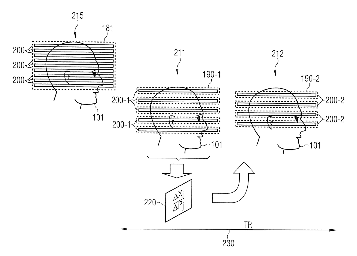
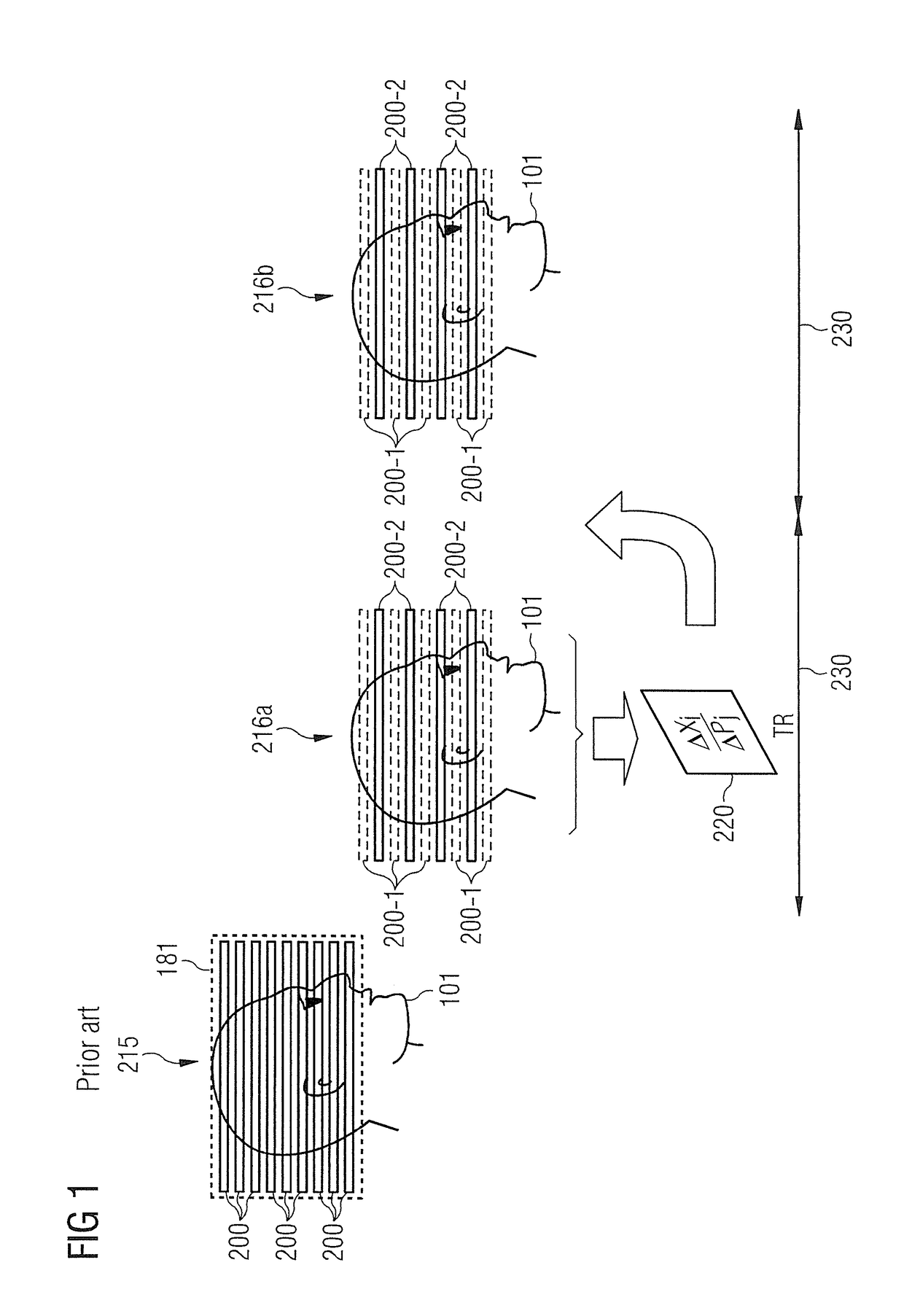
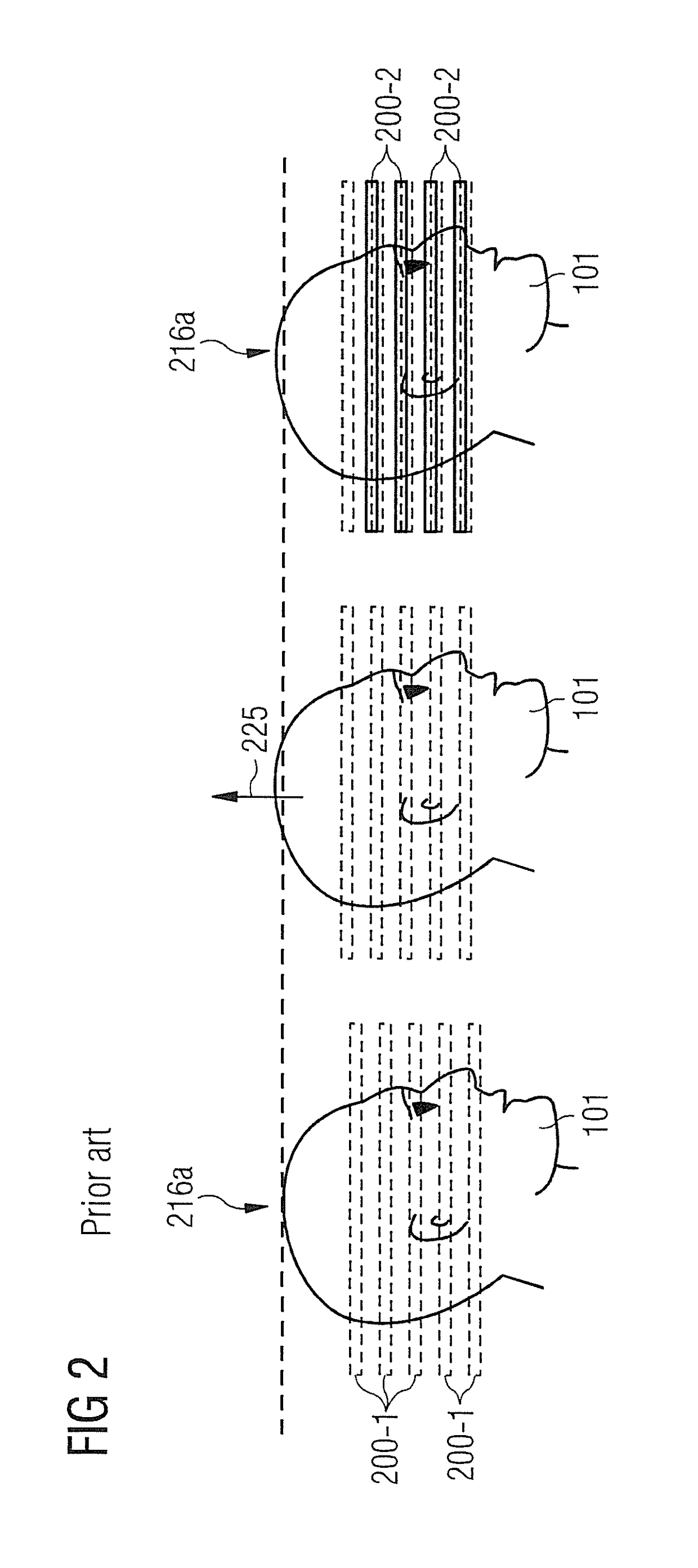
[0062]Techniques for prospective motion correction in MR imaging will now be explained. A region of interest to be imaged is subdivided ...


PUM


Abstract

For prospective motion correction in magnetic resonance imaging, first magnetic resonance data that map a first sub-region of a region of interest are acquired. Motion correction parameters are determined based on a comparison of at least the first magnetic resonance data with reference magnetic resonance data that map the region of interest. Second magnetic resonance data that map a second sub-region of the region of interest are determined using prospective motion correction based on the motion correction parameters. A magnetic resonance image is determined based on the first magnetic resonance data and based on the second magnetic resonance data.

Description

BACKGROUND OF THE INVENTION[0001]Field of the Invention[0002]The present invention concerns a method for magnetic resonance imaging using prospective motion correction and a corresponding magnetic resonance system.[0003]Description of the Prior Art[0004]In magnetic resonance (MR) imaging, an MR image is produced which maps a region of interest. A certain period of time (scan time) is typically required for obtaining the MR data. It may happen that an object being scanned moves during the scan time. This motion often reduces the MR image quality. For example, motion artifacts occur.[0005]Techniques for reducing motion artifacts (motion correction) are well known. Motion correction is often also termed motion compensation. Reduction can mean complete or partial elimination of the motion artifacts. In particular, so-called prospective motion corrections are known. Here information about the motion is obtained even during MR data acquisition (scanning) and this information is used for m...

Claims


Application Information

Patent Timeline
Patent Type & Authority Patents(United States)
IPC IPC(8): G01V3/00G01R33/565G01R33/48G01R33/483
CPCG01R33/56509G01R33/4835G01R33/4806
Inventor BECK, THOMAS
Owner SIEMENS HEALTHCARE GMBH
Why Eureka
Try Eureka