Eureka AIR delivers breakthrough ideas for toughest innovation challenges, trusted by R&D personnel around the world.

Method for fabricating LED lamp and high-output LED fabricated by using the method

a technology of led lamps and manufacturing methods, which is applied in the direction of basic electric elements, electrical equipment, semiconductor devices, etc., can solve the problems of long process time, complicated fabrication process, and inability to exhibit uniform heat release properties of leds fabricated by using the method

Inactive Publication Date: 2008-05-08
KOREA INST OF ENERGY RES
View PDF4 Cites 4 Cited by
  • Summary
  • Abstract
  • Description
  • Claims
  • Application Information

AI Technical Summary

Benefits of technology

[0012]It is another object of the present invention to provide a high-output LED, which has a simple structure and can exhibit improvement in heat release property, fabricated by using the method.

Problems solved by technology

As a result, the fabrication process is complicated.
In addition, it takes for a long time to perform the complicated process.
Accordingly, LEDs fabricated by using the method cannot exhibit uniform heat release property.

Method used


Image

  • Method for fabricating LED lamp and high-output LED fabricated by using the method
  • Method for fabricating LED lamp and high-output LED fabricated by using the method
  • Method for fabricating LED lamp and high-output LED fabricated by using the method

Examples


Embodiment Construction

[0021]Detailed description will be made of preferred embodiments of the present invention with reference to the accompanying drawings. However, various changes and modifications may be made to the preferred embodiments of the invention and the invention is not to be construed as being limited to the embodiments.

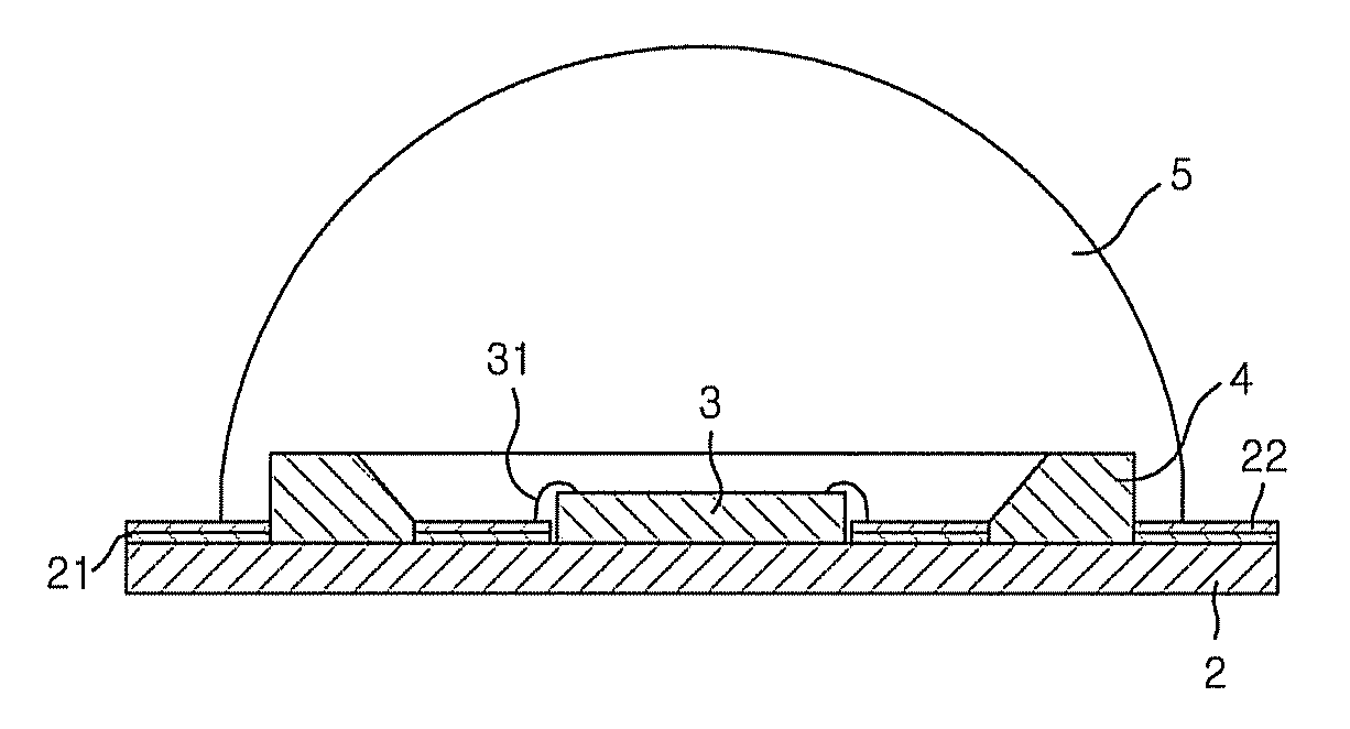
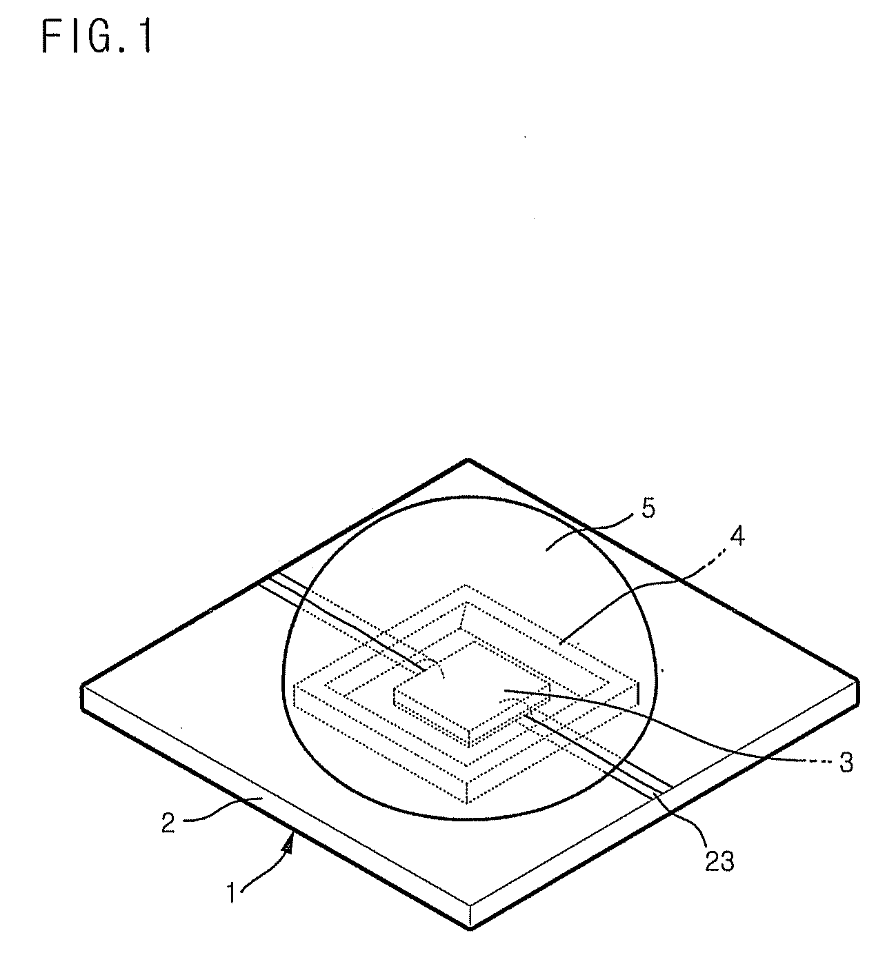
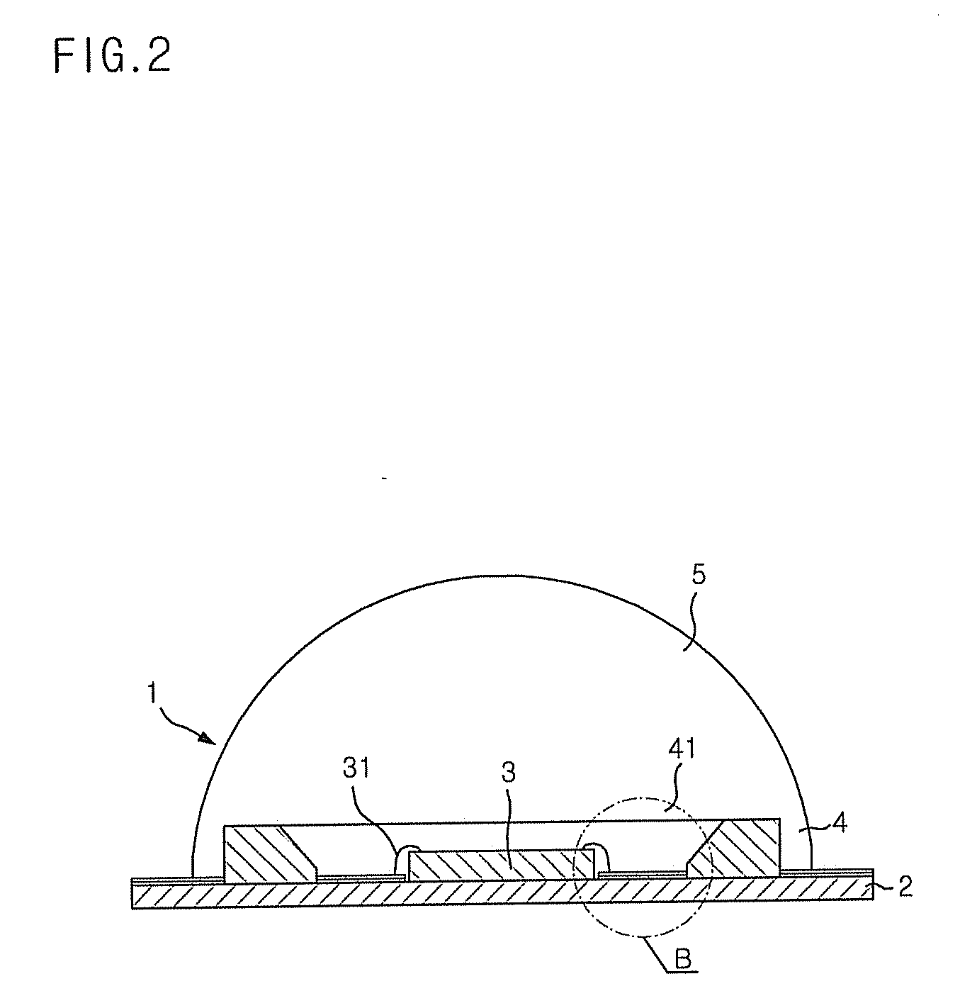
[0022]FIG. 1 is a perspective view illustrating a high-output LED according to the present invention. FIG. 2 is a cross-sectional view taken along the line A-A′ of FIG. 1. FIG. 3 is an enlarged view of an area B in FIG. 2.

[0023]As shown in FIGS. 1 to 3, a high-output LED 1 of the present invention includes a substrate 2, an insulating layer 21 coated on the substrate 2 and formed to have a predetermined pattern through an etching process. The high-output LED 1 also includes a metal layer 22 coated on the insulating layer 21 and formed to have a predetermined pattern through an etching process. The metal layer 22 has an electrode pattern including a recess on which an LED chip...


PUM


Abstract

A method for fabricating a light emitting diode lamp in a simplified procedure, and a high-output LED, that has a simple structure and can exhibit improvement in heat release property, fabricated by using the method which includes the steps of coating an insulating layer on a substrate and etching the insulating layer using a mask pack, coating a conductive metal layer on the insulating layer, forming an electrode pattern and a recess, on which an LED chip is mounted, on the metal layer using the mask pack, attaching the LED chip to the top of the recess, connecting a wire to the electrode pattern, and mounting a reflector having a vertical opening hole around the LED chip on the substrate to reflect light emitted from the LED chip in all directions, and molding the top of the substrate from a transparent resin to cover the LED chip, the electrode pattern and the reflector.

Description

[0001]This application claims priority to Korean Patent Application No. 10-2006-0109602, filed on Nov. 7, 2006, and all the benefits accruing therefrom under 35 U.S.C. §119, the contents of which are incorporated herein by reference in their entirety.BACKGROUND OF THE INVENTION[0002]1. Field of the Invention[0003]The present invention relates to a method for fabricating a light emitting diode lamp. More specifically, the present invention relates to a method for fabricating a light emitting diode lamp in a simplified procedure, and a high-output LED, that has a simple structure and can exhibit improvement in heat release property, fabricated by using the method.[0004]2. Description of the Related Art[0005]Light emitting diodes (hereinafter, referred to simply as “LEDs”) are formed of a variety of compound semiconductor materials (e.g., GsAs, AlGaAs, GaN etc.) acting as a light emitting source to emit light of various colors.[0006]In recent years, developments in semiconductor techni...

Claims


Application Information

Patent Timeline
Patent Type & Authority Applications(United States)
IPC IPC(8): H01L21/00H01L33/54H01L33/60H01L33/62
CPCH01L33/54H01L33/60H01L33/62H01L2224/48091H01L2924/10253H01L2924/00014H01L2924/00
Inventor JEONG, HAK-GEUNJUNG, BONG-MANHAN, SOO-BINSONG, YU-JINPARK, SUK-INYU, SEUNG-WONKIM, GYU-DUK
Owner KOREA INST OF ENERGY RES
Why Eureka
Eureka Blog
Learn More