Intervertebral spacers

a technology of intervertebral discs and spacers, which is applied in the field of intradiscal space and hollow intervertebral spacers, can solve the problems of affecting the stability of the spine, so as to prevent significant subsidence of the implant.

Inactive Publication Date: 2008-05-08
WARSAW ORTHOPEDIC INC
View PDF30 Cites 85 Cited by
  • Summary
  • Abstract
  • Description
  • Claims
  • Application Information

AI Technical Summary

Benefits of technology

[0012] In accordance with the invention, hollow spinal spacers having anatomically friendly shapes and features are provided for engagement between vertebrae. The spacers are sized and configured to fill a space between adjacent vertebrae and include an anterior wall having opposite ends, a posterior wall having opposite ends, and two lateral walls. The lateral walls are each connected between the opposite ends of the anterior and posterior walls to define a chamber. The walls also define a superior face having a first opening which is in communication with the chamber and an opposite inferior face having a second opening which is also in communication with the chamber. The superior and inferior faces each define vertebral engaging surfaces. In one specific embodiment, the spacer is D-shaped having a basic flat geometry and a convexly curved anterior surface on the anterior wall. The flat spacer provides a friction fit by virtue of roughened vertebral engaging surfaces. In another specific embodiment, the implant is smile-shaped, having a radius in the superior and inferior faces which match the shape of vertebral end-plates. In another aspect of this invention, spacers include a biconvex shape in addition to a smile contour. In still a further aspect of this invention, spacers are provided with vertebral engaging surfaces that include blades for driving into the bone. In another specific embodiment, hollow spacers of this invention include lateral wings which are extendable into the disc space to prevent significant subsidence of the implant into the vertebral bodies.
[0013] One object of the invention is to provide an implant for engagement between vertebrae which restores the intervertebral disc space and supports the vertebral column while promoting bone ingrowth. Another object of the present invention is to provide spinal spacers which avoid the problems associated with allograft and autograft, such as the need for trial and error trimming of graft material to fit the intradiscal space, donor site morbidity and disease transmission risks.

Problems solved by technology

Spinal discs may be displaced or damaged due to trauma, disease or aging.
The extruded nucleus pulposus may press on the spinal nerve, which may result in nerve damage, pain, numbness, muscle weakness and paralysis.
Intervertebral discs may also deteriorate due to the normal aging process or disease.
As a disc dehydrates and hardens, the disc space height will be reduced leading to instability of the spine, decreased mobility and pain.
Collapse of the disc space can cause instability of the spine, abnormal joint mechanics, premature development of arthritis or nerve damage, in addition to severe pain.
Unfortunately, the use of bone grafts presents several disadvantages.
Autografts, bone material surgically removed from the patient, can be undesirable because they may not yield a sufficient quantity of graft material.
The additional surgery to extract the autograft also increases the risk of infection and blood loss.
Furthermore, some patients complain that the graft harvesting surgery is more painful than the fusion surgery.
However, allografts can be disadvantageous because of the risk of disease transmission, immune reactions and religious objections.
Furthermore, allogenic bone does not have the osteoinductive potential of autogenous bone and therefore may provide only temporary support.
Both allograft and autograft present additional difficulties.
Graft alone may not provide the stability required to withstand spinal loads.
Internal fixation may prevent graft collapse but presents its own disadvantages such as the need for more complex surgery.
This trial and error approach increases the length of time required for surgery.
Furthermore, the graft material usually has a smooth surface which does not provide a good friction fit between the adjacent vertebrae.
Slippage of the graft may cause neural and vascular injury as well as collapse of the disc space.
Success of the discectomy and fusion procedure requires the development of a contiguous growth of bone to create a solid mass because the implant may not withstand the compressive loads on the spine for the life of the patient.

Method used


Image

  • Intervertebral spacers
  • Intervertebral spacers
  • Intervertebral spacers

Examples


Embodiment Construction

[0028] For the purposes of promoting an understanding of the principles of the invention, reference will now be made to the embodiments illustrated in the drawings and specific language will be used to describe the same. It will nevertheless be understood that no limitation of the scope of the invention is thereby intended, such alterations and further modifications in the illustrated devices, and such further applications of the principles of the invention as illustrated therein being contemplated as would normally occur to one skilled in the art to which the invention relates.

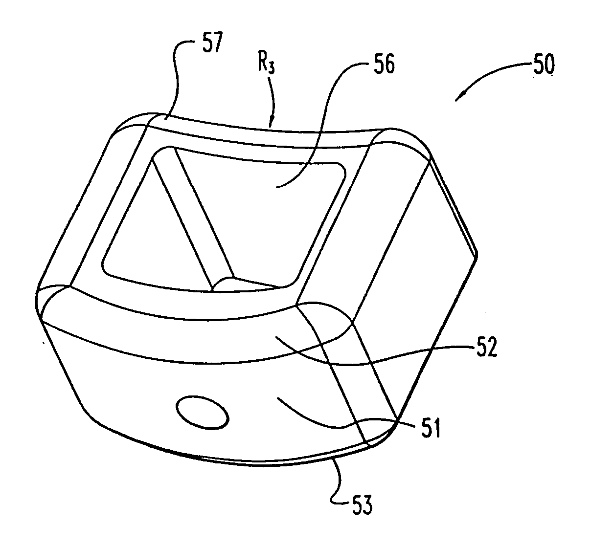
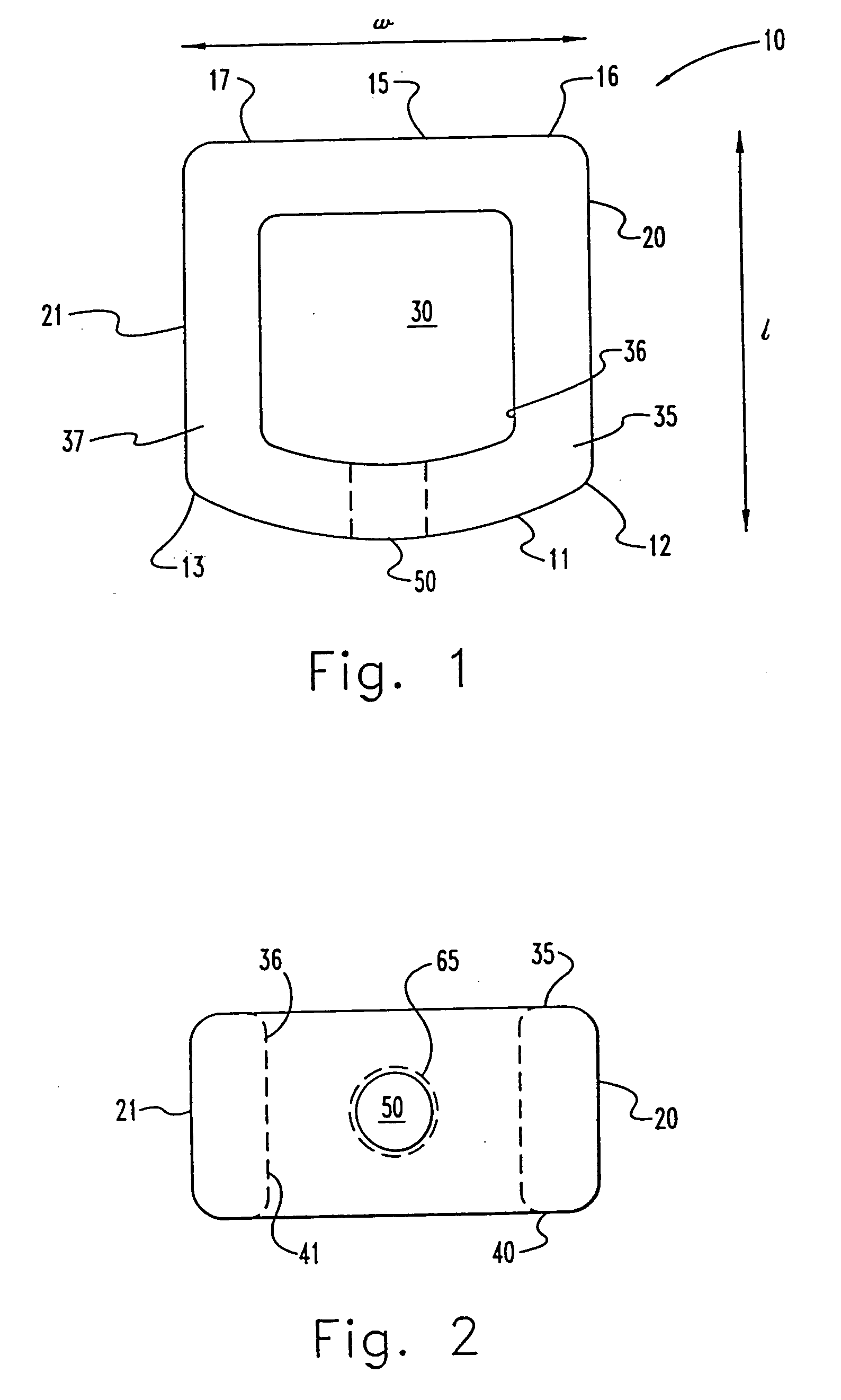
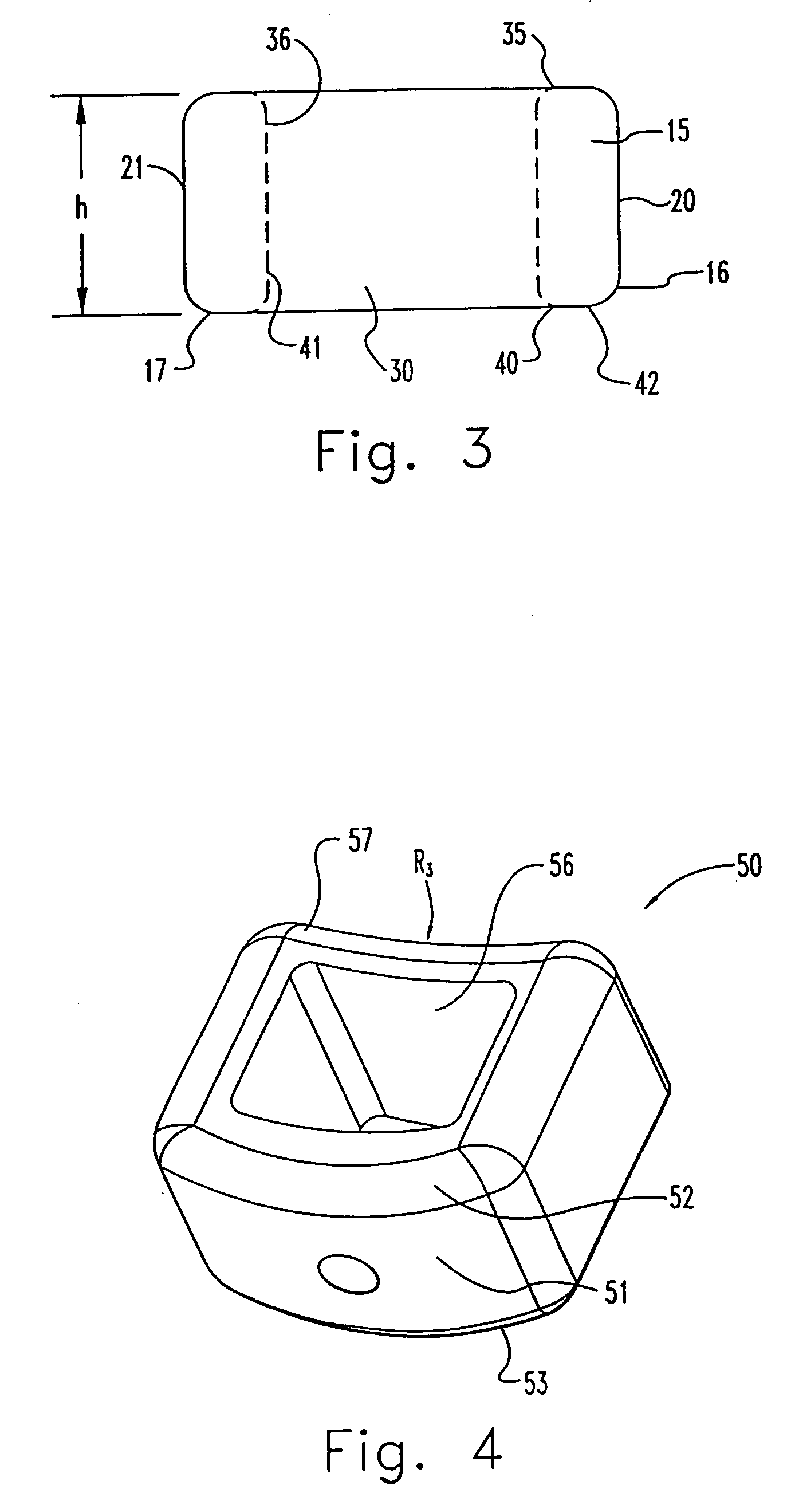
[0029] The present invention provides hollow spinal spacers for engagement between vertebrae which are sized and configured to fill the space left after discectomy. The inventive spacers restore height of the intervertebral disc space and provide immediate load bearing capability and support for the vertebral column without internal fixation. This invention eliminates the need for invasive autograft harvesti...


PUM

PropertyMeasurementUnit
Riaaaaaaaaaa
thickaaaaaaaaaa
heightaaaaaaaaaa

Abstract

One embodiment of a hollow spinal spacer (10) includes a curved anterior wall (11) having opposite ends (12, 13), a posterior wall (15) having opposite ends (16, 17), two lateral walls (20, 21), each integrally connected between the opposite ends (12, 13, 16, 17) of the anterior (11) and posterior (15) walls to define a chamber (30). The walls (11, 15, 20, 21) include a superior face (35) and an inferior face (40). The superior face (35) defines a first opening (36) in communication with the chamber (30) and includes a first vertebral engaging surface (37). The inferior face (40) defines a second opening (41) in communication with the chamber (30) and includes a second vertebral engaging surface (42).

Description

[0001] This application is a continuation-in-part application of Ser. No. 08 / 543,563, filed on Oct. 16, 1995.FIELD OF THE INVENTION [0002] The present invention broadly concerns devices for stabilizing the spine and devices for implantation between vertebrae, and more particularly in the intradiscal space. Specifically, the invention concerns hollow intervertebral spacers. BACKGROUND OF THE INVENTION [0003] Intervertebral discs, located between the end-plates of adjacent vertebrae, stabilize the spine, distribute forces between vertebrae and cushion vertebral bodies. A normal intervertebral disc includes a semi-gelatinous component, the nucleus pulposus, which is surrounded and confined by an outer, fibrous ring called the annulus fibrosus. In a healthy, undamaged spine, the annulus fibrosus prevents the nucleus pulposus from protruding outside the disc space. [0004] Spinal discs may be displaced or damaged due to trauma, disease or aging. Disruption of the annulus fibrous allows th...

Claims


Application Information

Patent Timeline
Patent Type & Authority Applications(United States)
IPC IPC(8): A61F2/44A61F2/00A61F2/02A61F2/28A61F2/30A61F2/46A61L31/02A61L31/04A61L31/06
CPCA61F2/30724Y10S606/908A61F2/442A61F2/4455A61F2/4611A61F2002/2817A61F2002/2835A61F2002/30062A61F2002/30112A61F2002/30153A61F2002/30187A61F2002/30261A61F2002/30271A61F2002/30677A61F2002/3092A61F2002/30929A61F2002/4475A61F2002/4623A61F2002/4627A61F2210/0004A61F2230/0004A61F2230/0019A61F2230/0034A61F2230/0082A61F2310/00161A61F2310/00293A61F2310/00491A61F2310/00544A61F2310/00796A61L31/024A61L31/026A61L31/044A61L31/047A61L31/048A61L31/06A61L2430/38Y10S606/907A61F2/30767A61F2002/30593A61F2/4603
Inventor VAN HOECK, JAMES E.MCDONALD, TROYCOATES, BRADLEY I.HAID, REGIS W. JR.HEIM, STEPHEN E.FOLEY, KEVINECKSTEIN, EUGENE C.
Owner WARSAW ORTHOPEDIC INC
Why Eureka
Try Eureka