Low cost, high purity sine wave generator

a sine wave generator, low cost technology, applied in the direction of instruments, computing, electric digital data processing, etc., can solve the problems of inability to determine whether the device operates as expected, defective devices that actually perform as expected, and inability to accurately test, etc., to achieve accurate circuitry, low cost, and high distortion

Inactive Publication Date: 2008-05-08
TERADYNE
View PDF8 Cites 18 Cited by
  • Summary
  • Abstract
  • Description
  • Claims
  • Application Information

AI Technical Summary

Benefits of technology

[0012]Low cost, and accurate circuitry for generating sinusoidal signals of a programmable frequency may be implemented by digitally generating a signal that approximates a sine wave. Though such a signal could produce a sine wave with high distortion if used directly, circuitry that corrects non-linearity errors may be used to reduce the distortion. The same circuitry that corrects for nonlinearity errors in a digital to analog converter or other portions of the test system used to generate the sine wave also may correct for nonlinearity errors introduced by using a digital signal that only approximates a sine wave.

Problems solved by technology

Inaccurate test signals lead to inaccurate test results, which in turn can lead to semiconductor devices that actually perform as expected being classified as defective devices and discarded.
Inaccuracy in test signals may also create uncertainty in test results such that, for some subset of devices tested, it is impossible to determine whether the device operates as expected.
When uncertainty precludes a determination of whether a device is operating correctly, the device is classified as defective and discarded.
Therefore, inaccurate signal generation in a tester can have a high cost associated with it.
Regardless of how the sinusoidal signal is used as a test signal, inaccuracies in generating the signal can impact the test results.
If the sinusoidal signal is applied directly to the device under test, the measured response may not be as expected—not because the device is defective, but because the test signal was not as expected.
If the sinusoidal signal is used for timing other events, the expected response may not be detected—not because the device failed to produce the response, but because the tester measured the response at the wrong time.

Method used


Image

  • Low cost, high purity sine wave generator
  • Low cost, high purity sine wave generator
  • Low cost, high purity sine wave generator

Examples


Embodiment Construction

[0026]The inventors have appreciated that a semiconductor test system may be improved with an accurate, programmable sinusoidal signal generator that is readily implemented at low cost as part of a test system. According to an embodiment of the invention, a sinusoidal signal generator is implemented without look-up tables to store a representation of the sinusoidal signal. As a result, the sinusoidal signal generator may be readily implemented within a field programmable gate array or other semiconductor device that has limited memory. Reducing the need for large amounts of memory to store a look-up table as part of a sinusoidal signal generator may be particularly desirable as part of an automatic test system that includes multiple sinusoidal signal generators.

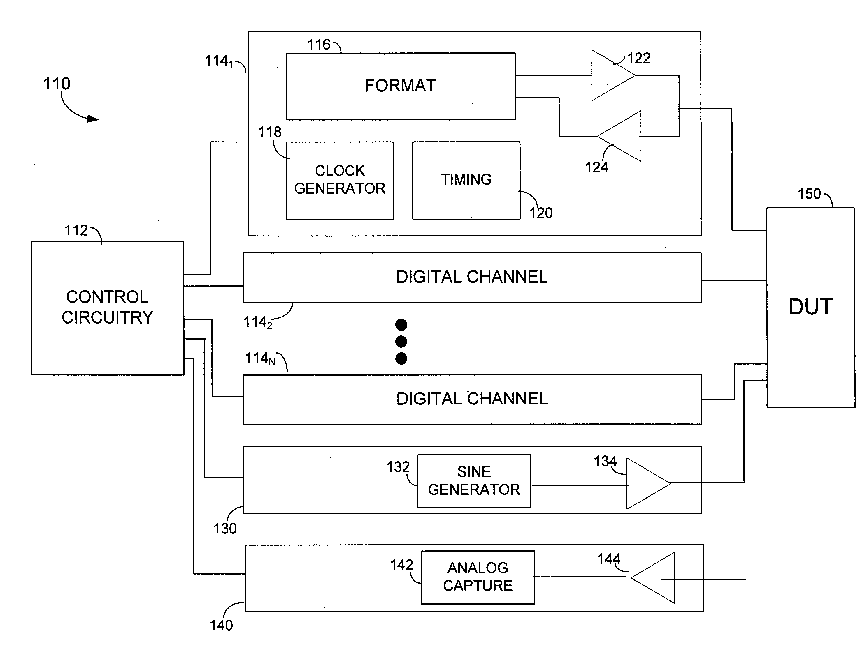
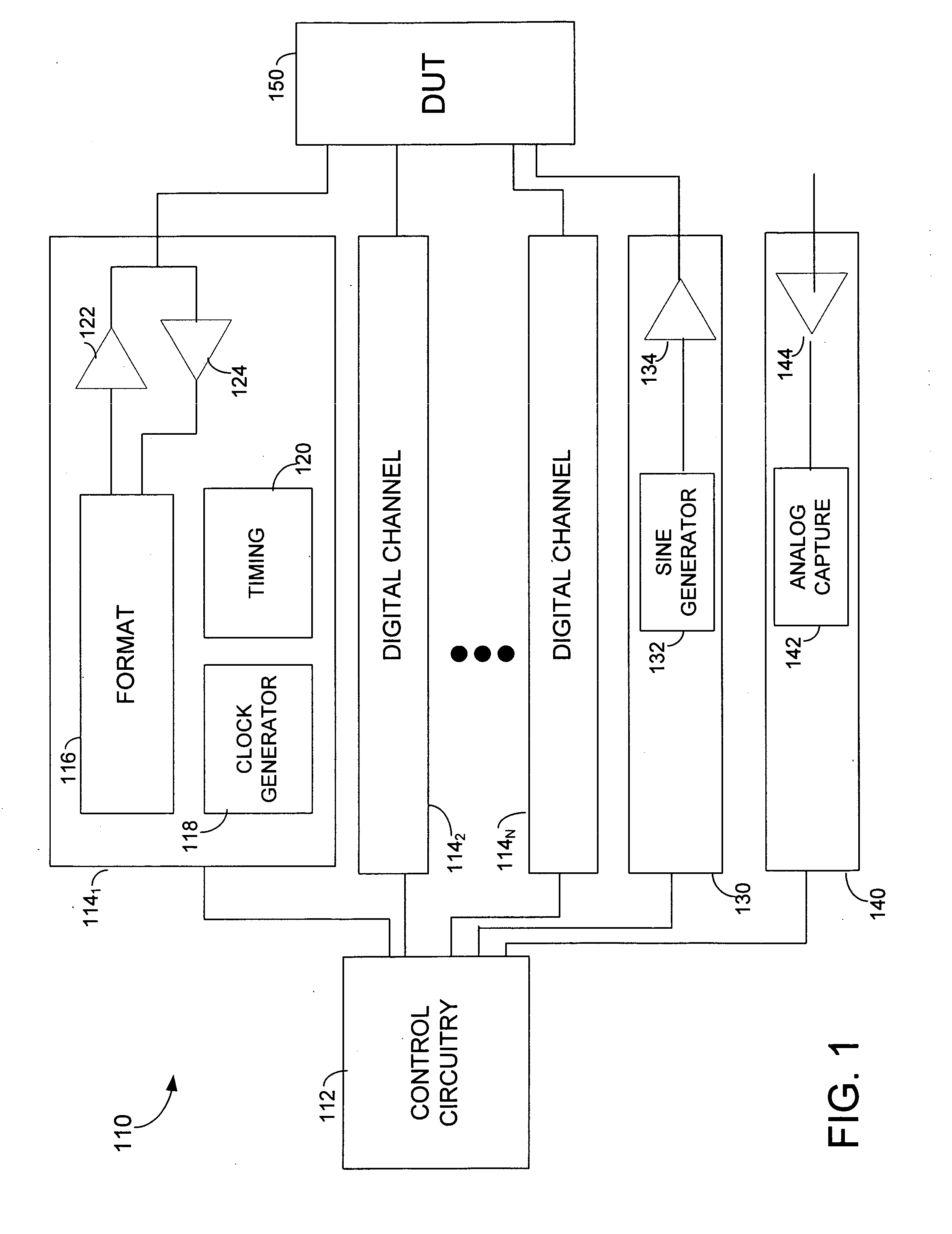
[0027]FIG. 1 illustrates an automatic test system that may employ one or more sinusoidal signal generators according to an embodiment of the invention. Test system 110 includes control circuitry 112. Control circuitry 112 may...


PUM


Abstract

An automatic test system that includes low cost and accurate circuitry for generating sinusoidal signals. Each sinusoidal signal generator produces a series of digital values approximating a sine wave. These values are computed, avoiding the need for large memories to store tables representing sine waves. Inaccuracies in the representation of the sine waves do not impact the accuracy of the resultant sine wave because circuitry used to correct for non-linearity errors in a digital-to-analog converter is programmed to also correct for errors introduced by approximating a sine wave with a computed function. A simple parabolic function may be used to compute approximations of a sine wave.

Description

BACKGROUND OF INVENTION[0001]1. Field of Invention[0002]The invention relates generally to automatic test equipment and more particularly to generation of signals for testing semiconductor devices.[0003]2. Discussion of Related Art[0004]Semiconductor devices are tested, often multiple times, during their manufacture. A piece of automatic test equipment, referred to as “ATE” or a “tester,” is used to generate test signals that stimulate a device under test (DUT) and to measure a response from the DUT. The tester determines whether the DUT is operating properly by comparing the response evoked by a carefully controlled pattern of test signals with an expected response.[0005]To fully test devices, the tester should generate and measure signals like those in the intended operating environment of those devices. Because numerous types of semiconductor devices need to be tested, automatic test equipment is designed to be programmable so that it may generate or measure the signals needed to...

Claims


Application Information

Patent Timeline
Patent Type & Authority Applications(United States)
IPC IPC(8): G06F1/02
CPCG06F1/0328G06F1/022
Inventor MCDONALD, WILLIAM SCOTT
Owner TERADYNE
Why Eureka
Try Eureka