Engine cover

Inactive Publication Date: 2008-05-15
TOYODA GOSEI CO LTD
View PDF5 Cites 8 Cited by
  • Summary
  • Abstract
  • Description
  • Claims
  • Application Information

AI Technical Summary

Benefits of technology

[0009]The present invention has been made in view of the above problems, and provides an engine cover

Problems solved by technology

When the step is generated at a joint between the divisional bodies, the divisional bodies can be not arranged on the coplanar surface, and thus the design of the engine room may be deteriorated.
As a result, a noise is generated.
However, in the structure which is assembled by the divisional bodies disclosed in the Japanese Laid Open patent Publication No. 7-2

Method used


Image

  • Engine cover
  • Engine cover
  • Engine cover

Examples


first embodiment

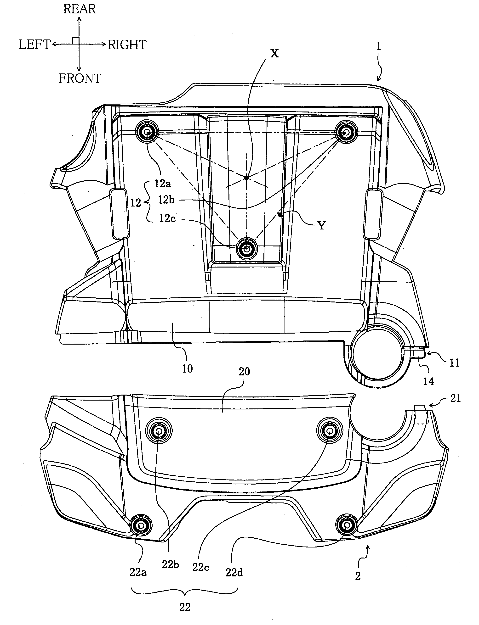
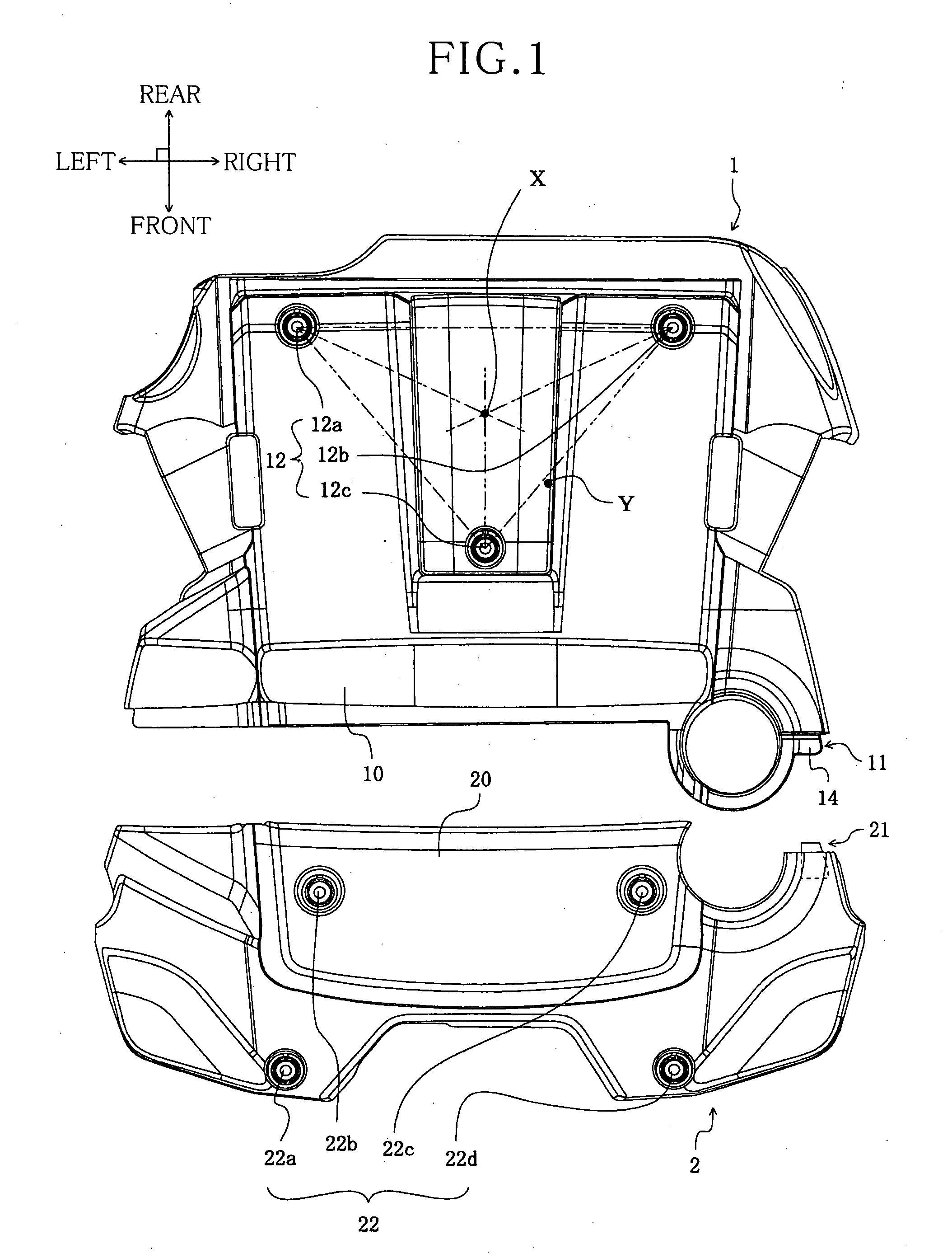
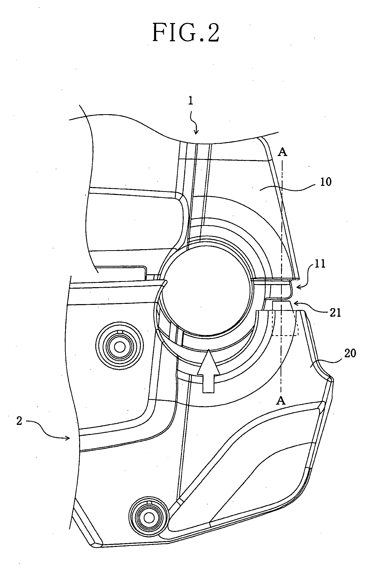
[0045]An engine cover in accordance with a first embodiment of the present invention includes one mounting structure portion. The engine cover according to the first embodiment includes the above-described (1), (2), (5) and (6). FIG. 1 is a top view schematically illustrating an engine cover in accordance with a first embodiment of the present invention. FIG. 2, FIG. 4 and FIG. 6 are enlarged top views of a main part schematically illustrating an appearance of a first divisional body and a second divisional body in an engine cover assembled to an engine side member in accordance with a first embodiment of the present invention. FIG. 3, FIG. 5, FIG. 7 and FIG. 8 are enlarged sectional views of a main part schematically illustrating an appearance of a first divisional body and a second divisional body in an engine cover assembled to an engine side member in accordance with a first embodiment of the present invention. FIG. 3 refers to an appearance of cutting the first divisional body ...

second embodiment

[0066]The engine cover of the second embodiment is the same as the engine cover of the first embodiment except for including three groups of mounting structure portions. FIG. 9 is a top view schematically illustrating the engine cover in accordance with the second embodiment of the present invention. Hereinafter, a front, a rear, a left and a right in the second embodiment indicate a front, a rear, a left and a right shown in FIG. 9. In the Second Embodiment, note that the term, “up,” specifies the direction toward the viewer of FIG. 9, and the term, “down,” specifies the direction away from the sheet of FIG. 9.

[0067]The first divisional body 1 in the engine cover of the second embodiment includes three first mounting end portions 110, 111 and 112. The three first mounting end portions 110, 111 and 112 are provided in the front end portion of the first cover main body 10. In particular, a right side first mounting end portion 110 which is one of the first mounting end portions is pr...

third embodiment

[0072]The engine cover according to the third embodiment includes the above-described (1), (4) and (6). The engine cover of the third embodiment is the same as the engine cover of the first embodiment except for a shape of the first mounting end portion, a shape of the second mounting end portion and a position of the cushion body. FIG. 10 is an enlarged sectional view of a main part schematically illustrating an appearance of the first divisional body and the second divisional body in the engine cover assembled to the engine side member in accordance with the third embodiment of the present invention. Hereinafter, a front, a rear, an up and a down in the third embodiment indicate a front, a rear, an up and a down shown in FIG. 10.

[0073]The second mounting end portion 21 in the engine cover of the third embodiment includes the second engaging end portion 24, but doesn't include the second leg portion. The second engaging end portion 24 is continued to the second cover main body 20 a...


PUM


Abstract

An engine cover which can improve the assembly work and prevent noise generated at a joint between divisional bodies is provided. A first divisional body of the engine cover includes a first cover main body and a first mounting end portion provided to one end portion of the first cover main body, and a second divisional body of the engine cover includes a second cover main body and a second mounting end portion provided to one end portion of the second cover main body. The first mounting end portion is provided with a first engaging end portion arranged in a down direction of the first cover main body and extending in a diametric direction outwardly thereof. The second mounting end portion is provided with a second engaging end portion arranged in a down direction of the second cover main body and extending in a diametric direction outwardly thereof. At least one portion of the second engaging end portion is arranged in an inner circumferential side of the second cover main body from an outer circumferential end portion thereof. The first engaging end portion is held between the second engaging end portion and a main body side engaging portion which is one portion of the second cover main body to integrate the first divisional body and the second divisional body. A cushion body formed of an elastic material is mounted between the first engaging end portion and the main body side engaging portion and/or between the first engaging end portion and the second engaging end portion.

Description

INCORPORATION BY REFERENCE[0001]This disclosure of Japanese Patent Application No. 2006-308244 filed on Nov. 14, 2006 and Japanese Patent Application No. 2007-249035 filed on Sep. 26, 2007, including the specification, drawings, and abstract is incorporated by reference in its entirety.BACKGROUND OF THE INVENTION[0002]1. Field of the Invention[0003]The present invention relates to an engine cover for covering an upper surface of an engine side member in a vehicle.[0004]2. Description of the Related Art[0005]An engine room of a vehicle is provided with an engine side member. The engine side member is integrated by assembling members such as an engine, a cylinder head cover or the like. The upper surface of the engine side member is generally covered with an engine cover. The engine cover covers the engine side member so as to improve the design of the engine room and to shut out or attenuate noise emitted outwards from the engine. The engine cover is designed in the various shapes ac...

Claims


Application Information

Patent Timeline
IPC IPC(8): F16M1/02
CPCF02F7/006F02B77/13
Inventor NONOGAKI, HARUHIKO
Owner TOYODA GOSEI CO LTD
Why Eureka
Try Eureka