Burnpot for solid particulate stove

Inactive Publication Date: 2008-05-15
HNI TECH INC
View PDF13 Cites 5 Cited by
  • Summary
  • Abstract
  • Description
  • Claims
  • Application Information

AI Technical Summary

Benefits of technology

[0010]One advantage of the invention is that providing air both over and under the burning fuel promotes cleaner burning, resulting in the reduction of carbon buildup in the burnpot and reducing the need for cleaning the burnpot.
[0011]Another advantage of the invention is that cleaner burning reduces sticky creosote residue build up on heat exchangers, resulting in heat exchangers that operate more efficiently.
[0012]Yet another advantage of the invention is that cleaner burning can additionally be achieved by reducing the size and increasing the number of holes in the grates, reducing emissions levels of noxious pollutants, such as carbon monoxide.
[0013]Still another advantage of the invention is

Problems solved by technology

This has a tendency to provide too much air at one spot, which can lead to improper combustion and formation of carbon.
By only using standard hole sizes of 0.125 in. and larger in diameter, as seen in conventional burn pots, high volumetric flow of air has a tendency to cool the hot coals as it blows past, reducing the efficiency of the burn.
This efficiency is further decreased because these higher volumes of air also tend to sweep volatile components from the fuel, which are carried away in the exhaust, leaving ash and residue that cannot be burnt to completion.
Furthermore, particulate fuels can clump toget

Method used


Image

  • Burnpot for solid particulate stove
  • Burnpot for solid particulate stove
  • Burnpot for solid particulate stove

Examples


Example

[0024]Where like parts appear in more than one drawing, it has been attempted to use like reference numerals for clarity.

DETAILED DESCRIPTION OF EXEMPLARY EMBODIMENTS

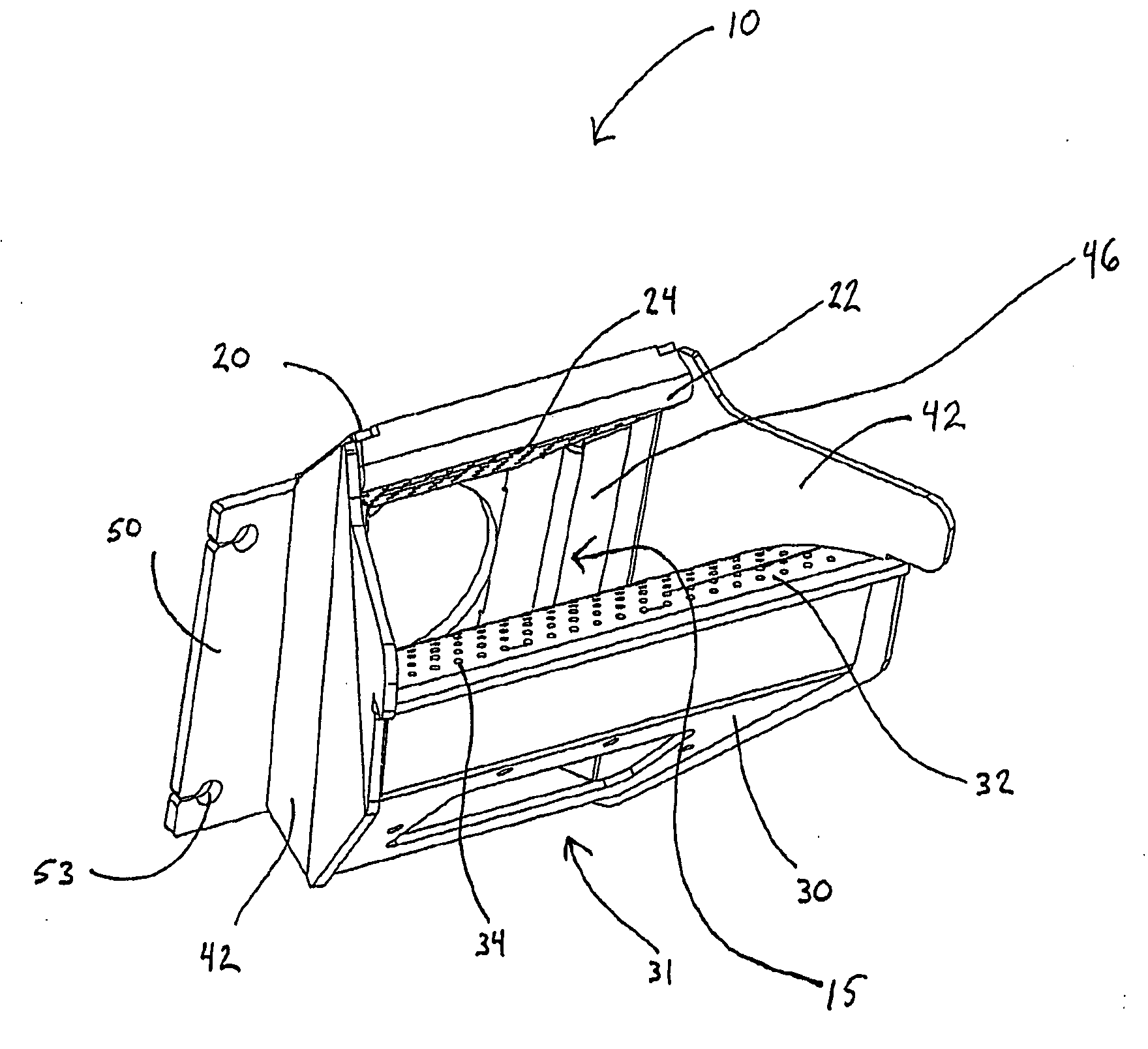
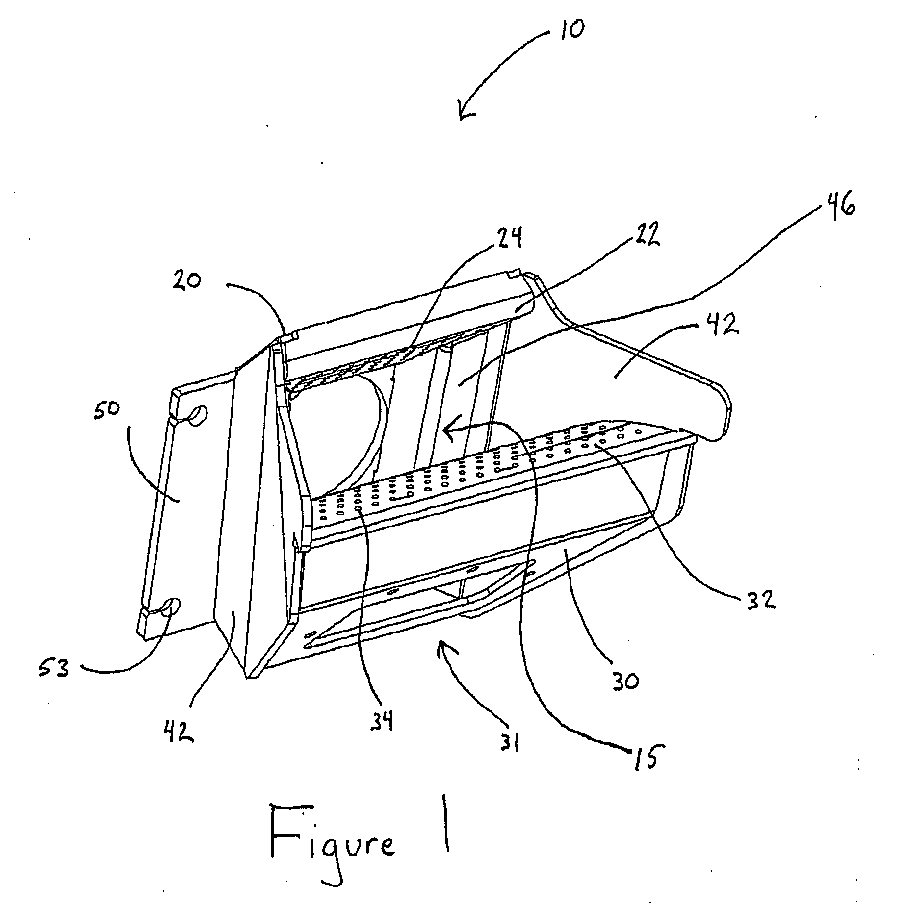
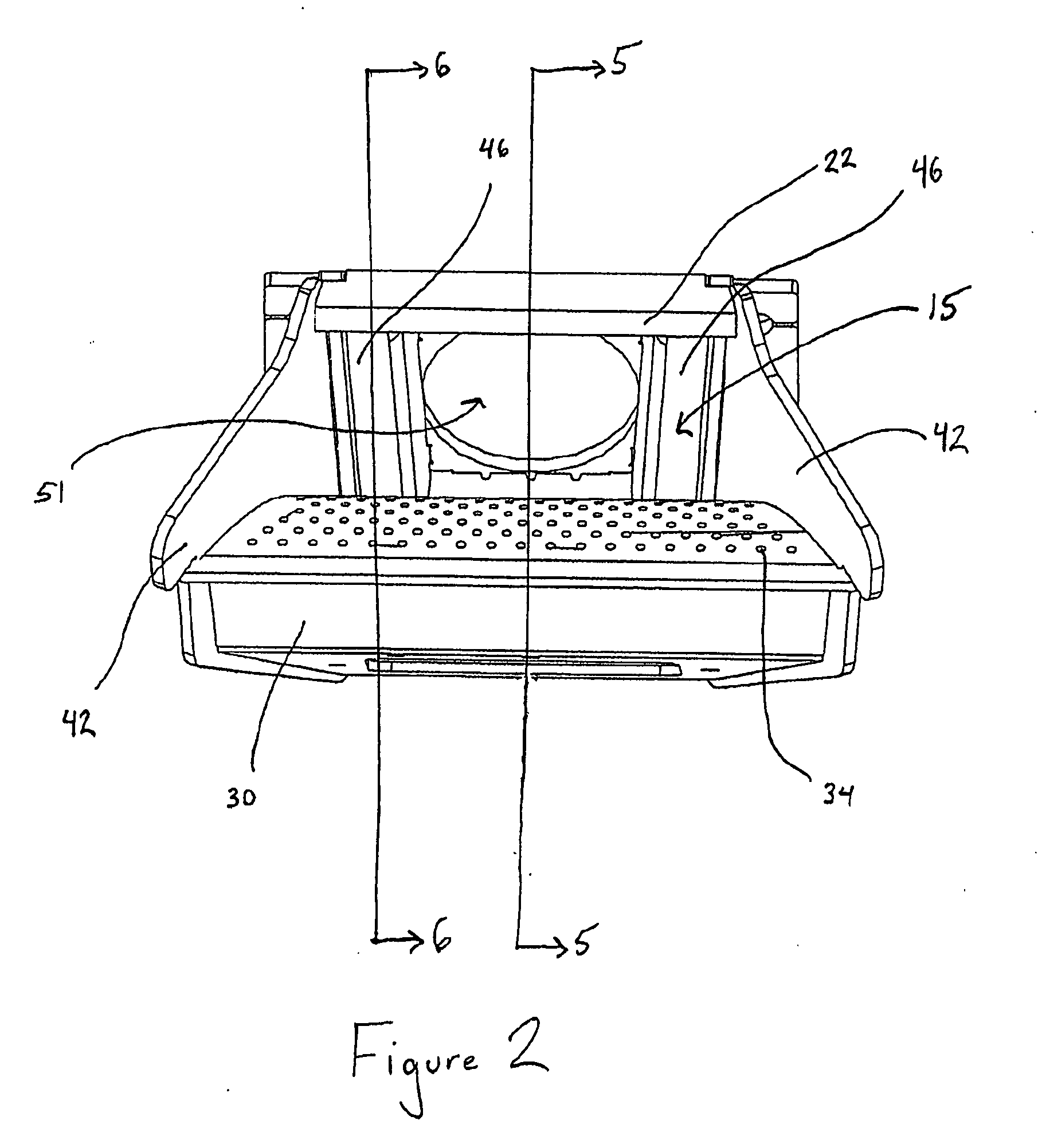
[0025]FIG. 7 illustrates a generalized sectional view of a solid particulate stove 100 in accordance with an exemplary embodiment of the invention. The stove 100 includes a hopper 6 in which fuel (not shown), such as wood pellets, wood chips, grains (e.g., shelled corn, barley, wheat, etc.), pelletized biofuels, anthracite coal, walnut shells, peach pits and the like, by way of example, or any other suitable particulate fuel or fuel mixture is stored prior to burning. The stove 100 also includes a feed system 2 that includes an auger 4 to feed fuel from the hopper 6 to a burnpot 10 positioned in a heavily insulated firebox 8. There, the fuel is mixed with oxygen and burned. One or more heat exchangers 5, typically with at least one surface positioned in the firebox 8, are provided to transfer heat from the firebox 8 to ...


PUM


Abstract

A burnpot for a solid particulate stove is disclosed. The burnpot includes a bottom cover, a top cover, two side plates connecting the top cover and the bottom cover, a bottom grate having a plurality of bottom grate apertures disposed therein and positioned intermediate the bottom cover and the top cover, a top grate having a plurality of top grate apertures disposed therein and positioned intermediate the bottom grate and the top cover and an air passageway configured to direct air to a burn chamber of the burnpot through the bottom grate and the top grate.

Description

CROSS-REFERENCE TO RELATED APPLICATIONS[0001]This application claims the benefit of U.S. Provisional Application No. 60 / 865,240, filed Nov. 10, 2006, which is hereby incorporated by reference in its entirety.FIELD OF THE INVENTION[0002]The present invention relates generally to a burnpot for stoves that burn solid particulate fuels.BACKGROUND OF THE INVENTION[0003]Stoves that burn solid particulate fuels such as wood pellets, shelled corn, and pulverized coal for home heating are very popular. These stoves have a container or burnpot that contains and holds burning fuel, while air is provided through holes in the bottom of the burnpot to provide a flow of oxygen for combustion. Until now, these hole sizes have been 0.125 in. and larger in diameter. This has a tendency to provide too much air at one spot, which can lead to improper combustion and formation of carbon. Also, in some cases, these holes also allow ash and saw dust or other fuel fines to fall through the holes into the ai...

Claims


Application Information

Patent Timeline
IPC IPC(8): F24C1/14F24B13/04
CPCF23B40/08F24B1/195F23L1/02F23B60/02
Inventor GROSS, LARRY H.HARMAN, DANEMAGUIRE, CHARLES J.
Owner HNI TECH INC
Why Eureka
Try Eureka