
Defective Particle Measuring Apparatus and Defective Particle Measuring Method

Active Publication Date: 2008-05-15
OPTIMA
View PDF4 Cites 3 Cited by
  • Summary
  • Abstract
  • Description
  • Claims
  • Application Information

AI Technical Summary

Benefits of technology

[0010]The present invention has been made in consideration of the above circumstances, and has as its object to provide a defective particle measurement apparatus and a defective particle measurement method that can determine the size of defective particles in a short time with high precision using a simple constitution and can determine the density distribution of defective particles.
[0019]In the defective particle measuring apparatus and defective particle measuring method of the present invention, a position deviation computing means, based on an in-plane intensity distribution of scattered light of each defective particle that is imaged, obtains a deviation from a focal point position on an image point side of the scattered light of the each defective particle and calculates a position deviation amount in a depth direction of the defective particle corresponding to the deviation from the focal point position, a light intensity correcting means corrects the light intensity of the scattered light of the defective particle corresponding to the position deviation amount in the depth direction, a size determining means determines the size of the defective particle based on the light intensity corrected by the light intensity correcting means, and moreover a density computing means divides the position deviation amount in the depth direction into a plurality of ranges, obtains the number of defective particles that exist within each range, and computes a distribution density of the defective particles in the depth direction from a focal point position on an object point side of an imaging optical system. Therefore, it is possible to determine the size of defective particles in a short time with high precision using a simple constitution of acquiring, for example, only one two-dimensional defective particle image and possible to obtain the density distribution of the defective particles.

Problems solved by technology

Therefore, it is not possible to determine the size of the defective particles only by the scattering intensity.
However, since it is necessary to obtain a plurality of cross-sectional images in the method that is disclosed in Patent Document 2, the problem arises of the measurement taking time.

Method used


Image

  • Defective Particle Measuring Apparatus and Defective Particle Measuring Method
  • Defective Particle Measuring Apparatus and Defective Particle Measuring Method
  • Defective Particle Measuring Apparatus and Defective Particle Measuring Method

Examples


Embodiment Construction

[0065]Hereinbelow, a defective particle measuring apparatus and a defective particle measuring method that are the best mode for carrying out the present invention shall be described.

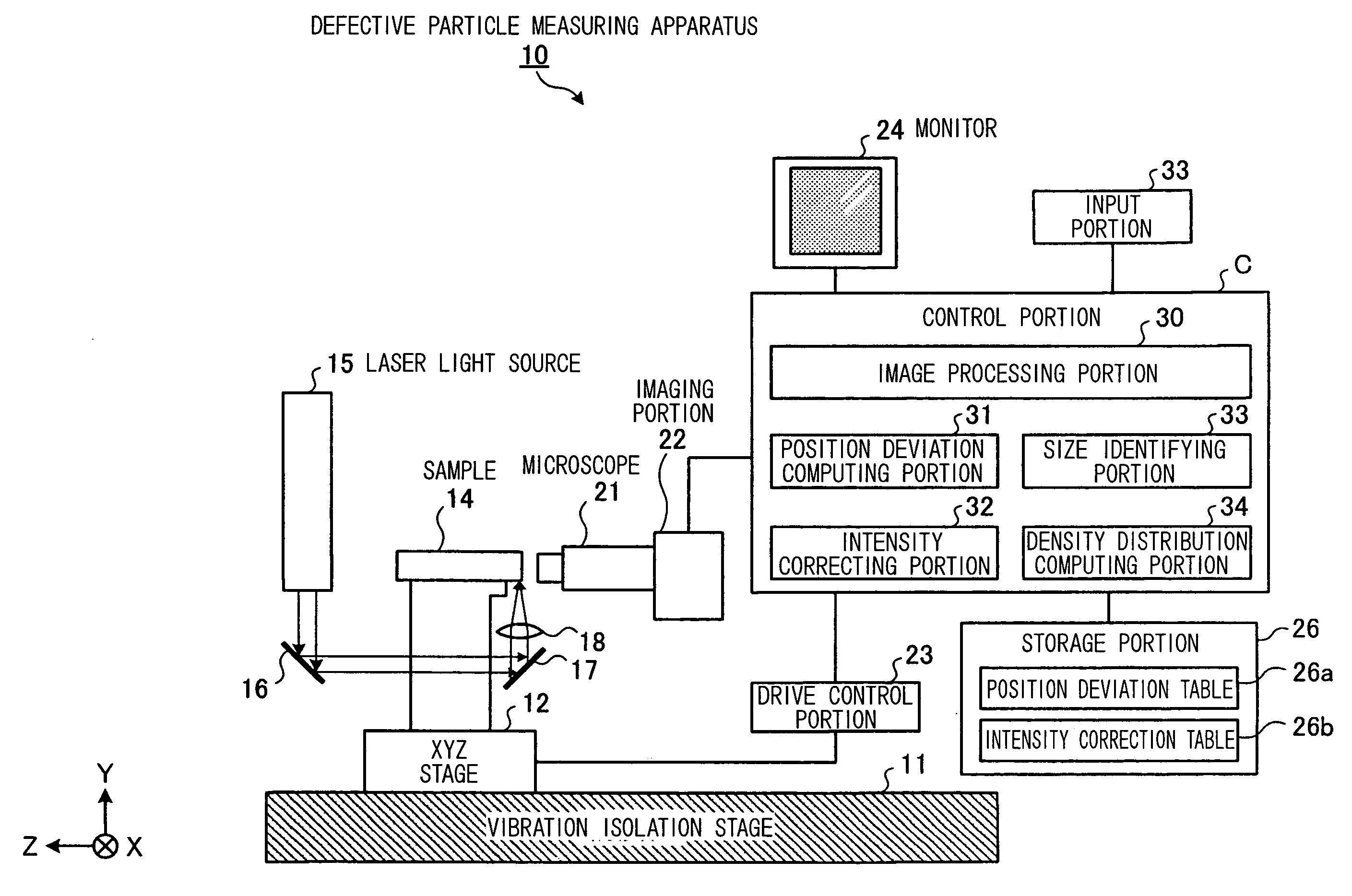
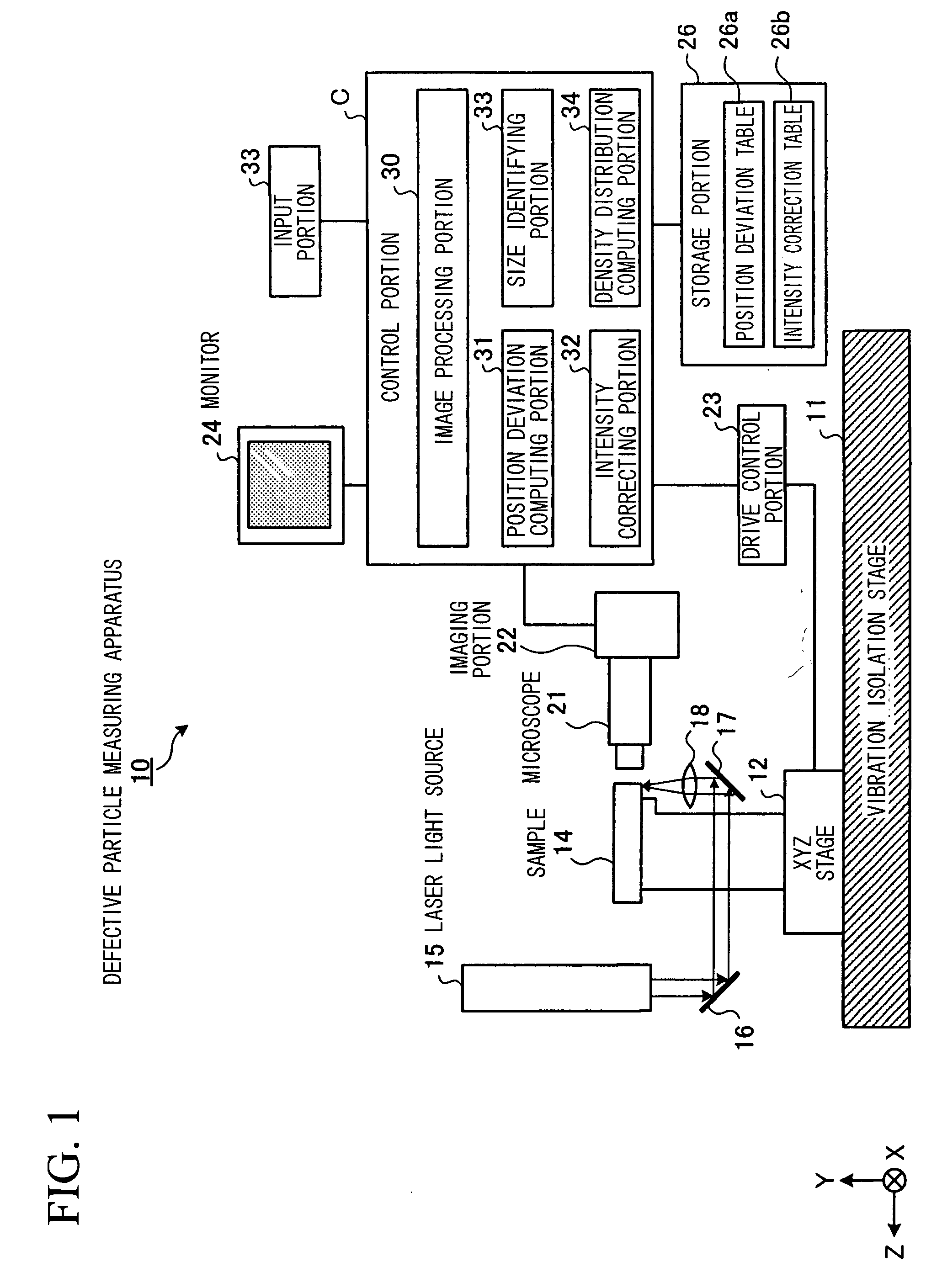
[0066]FIG. 1 is a block diagram showing the constitution of a defective particle measuring apparatus that is an embodiment of the present invention. In FIG. 1, a defective particle measuring apparatus 10 has an XYZ stage 12 disposed on a vibration isolation stage 11, and a sample 14 such as a semiconductor wafer disposed on the XYZ stage 12 via a sample stage 13. Laser light that is emitted from a laser light source 15 is irradiated via mirrors 16 and 17 and a condenser lens 18 from the Y direction of the sample 14. The laser light that is irradiated is scattered by defective particles in the sample 14, and a defective particle image is imaged by an imaging portion 22 via an optical system that is realized by a microscope 21 disposed in the −Z direction.

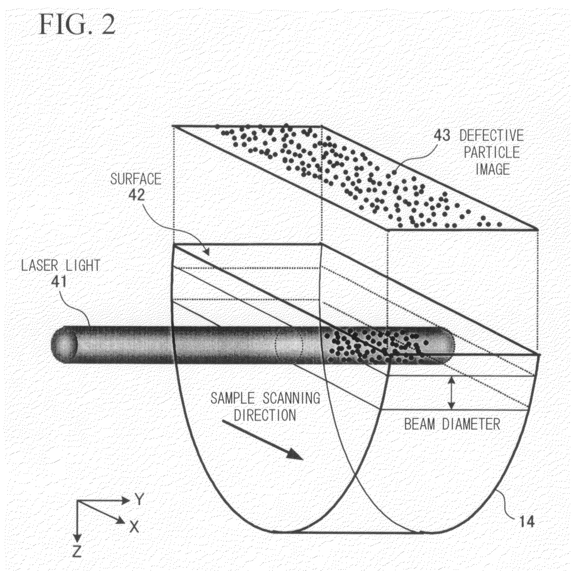
[0067]As shown in FIG. 2, laser light 41 that is c...


PUM


Abstract

A defective particle measuring apparatus that irradiates focused laser light on a sample, images scattered light from the sample, and measures defective particles in the sample based on the image result, includes a position deviation computing portion which, based on an in-plane intensity distribution of scattered light of each defective particle that is imaged, obtains a deviation from a focal point position on an image point side of the scattered light of each defective particle and calculates a position deviation amount in a depth direction of the defective particle corresponding to the deviation from the focal point position, a light intensity correcting portion for correcting the light intensity of the scattered light of the defective particle corresponding to the position deviation amount in the depth direction, and a size determining portion for determining the defective particle size based on the light intensity corrected by the light intensity correcting portion. Thus, the size of the defective particles can be determined at a high precision by a simple constitution in a short time, and density distribution of the defective particles can be obtained.

Description

TECHNICAL FIELD[0001]The present invention relates to a defective particle measurement apparatus and a defective particle measuring method that irradiate focused laser light on a sample, image scattered light from the sample, and measure defective particles in the sample based on the image result.BACKGROUND ART[0002]There have conventionally been apparatuses that irradiate focused laser light on a sample, image scattered light from the sample, perform predetermined image processing on the picked up image, and measure the density distribution of defective particles in the sample based on the image processing result (refer to Patent Document 1). According to this method, as shown in FIG. 3 or FIG. 4, a two-dimensional image is obtained using the 90-degree scattering method by which it is possible to know the two-dimensional placement of defective particles by imaging the laser light that is scattered by the defective particles in the sample.[0003]Patent Document 1: JP 2604607 (Japanes...

Claims


Application Information

Patent Timeline
IPC IPC(8): G01N15/02
CPCG01B11/0608G01N15/1463H01L22/10G01N2015/1452G01N21/8806G01N15/1433G01B11/02G01N21/47H01L22/00
Inventor MORIYA, KAZUO
Owner OPTIMA
Learn More