Electron absorption apparatus for an x-ray device

a technology of x-ray device and absorption apparatus, which is applied in the direction of x-ray tubes, nuclear engineering, nuclear elements, etc., can solve the problems of reducing the image quality of x-ray tubes, increasing the cost of providing additional cooling capacity, and affecting the durability of x-ray tubes

Active Publication Date: 2008-05-15
GENERAL ELECTRIC CO
View PDF11 Cites 24 Cited by
  • Summary
  • Abstract
  • Description
  • Claims
  • Application Information

AI Technical Summary

Problems solved by technology

The backscattered electrons can re-impact the anode and produce off-focus x-rays that diminish x-ray image quality.
Excess heat generatio

Method used


Image

  • Electron absorption apparatus for an x-ray device
  • Electron absorption apparatus for an x-ray device
  • Electron absorption apparatus for an x-ray device

Examples


Embodiment Construction

[0014]In the following detailed description, reference is made to the accompanying drawings that form a part hereof, and in which is shown by way of illustration specific embodiments that may be practiced. These embodiments are described in sufficient detail to enable those skilled in the art to practice the embodiments, and it is to be understood that other embodiments may be utilized and that logical, mechanical, electrical and other changes may be made without departing from the scope of the embodiments. The following detailed description is, therefore, not to be taken as limiting the scope of the invention.

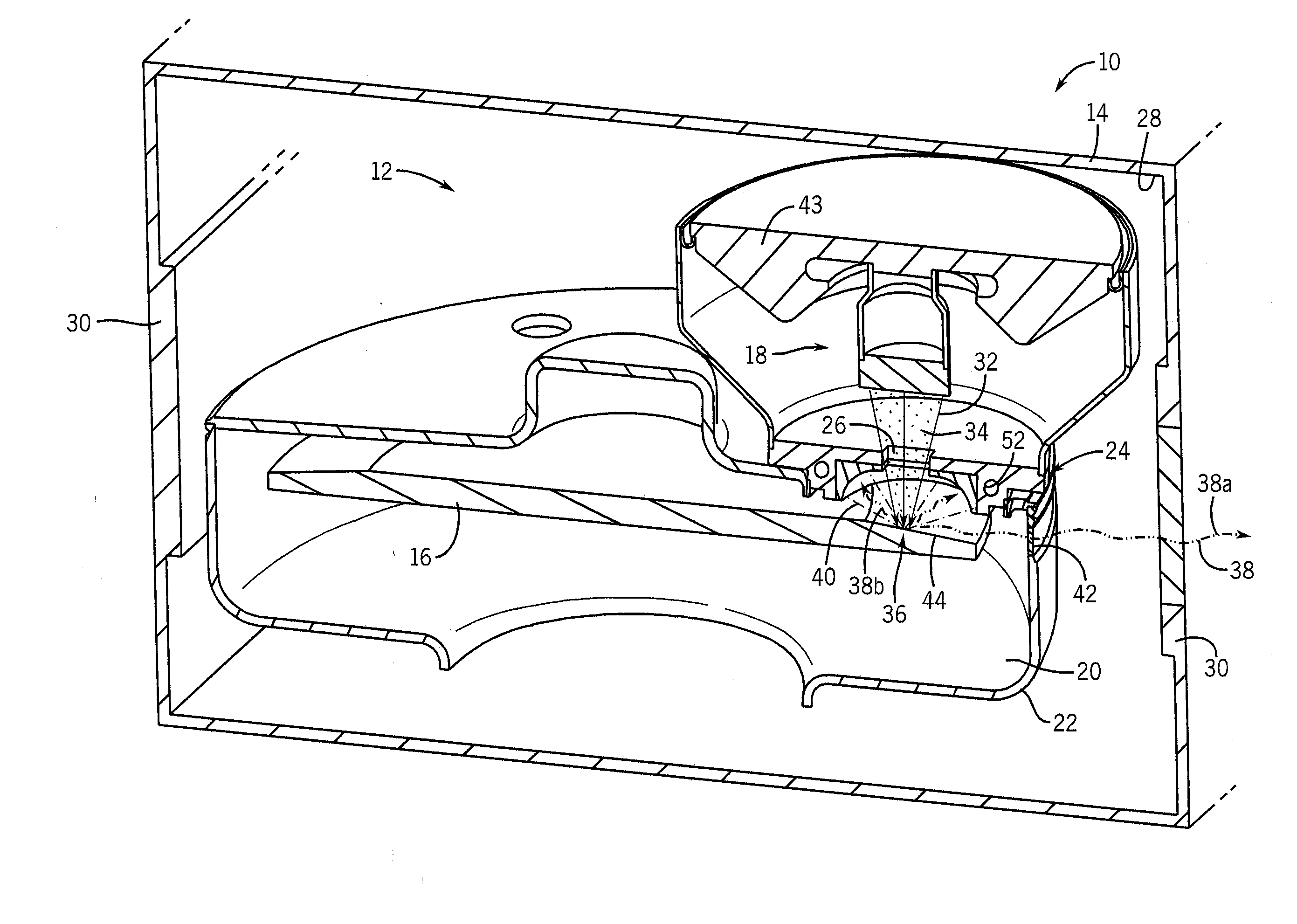
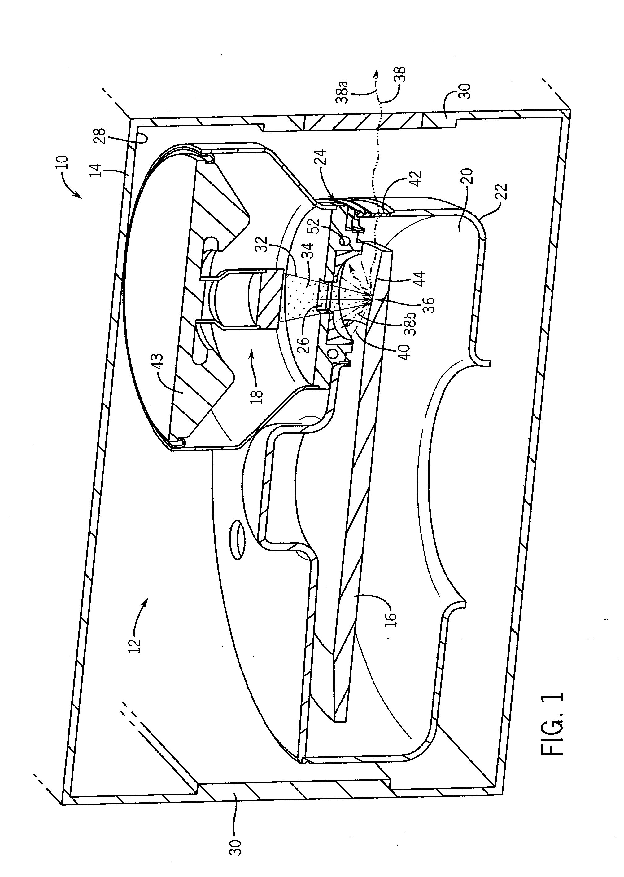
[0015]Referring to FIG. 1, a perspective sectional view of an x-ray device 10 in accordance with an embodiment is shown. The x-ray device 10 includes an x-ray tube insert 12 disposed in the schematically depicted casing 14. The x-ray tube insert 12 includes an anode 16 and a cathode assembly 18 which are at least partially disposed in a vacuum 20 within a vacuum enclosure or v...


PUM


Abstract

A shield assembly for an x-ray device is disclosed herein. The shield assembly includes a radiation shielding layer comprised of a first material; and a thermally conductive layer attached the radiation shielding layer. The thermally conductive layer is comprised of a second material. The shield assembly also includes an electron absorption layer attached to the radiation shielding layer. The electron absorption layer is comprised of a third material. The electron absorption layer is configured to absorb backscattered electrons.

Description

FIELD OF THE INVENTION[0001]This disclosure relates generally to an electron absorption apparatus for an x-ray device.BACKGROUND OF THE INVENTION[0002]X-ray tubes generally include a cathode and an anode disposed within a vacuum vessel. The cathode is positioned at some distance from the anode, and a voltage difference is maintained therebetween. The anode includes a target track or impact zone that is generally fabricated from a refractory metal with a high atomic number, such as tungsten or any tungsten alloy. The anode is commonly stationary or a rotating disc. The cathode emits electrons that are accelerated across the potential difference and impact the target track of the anode at high velocity. As the electrons impact the target track, the kinetic energy of the electrons is converted to high-energy electromagnetic radiation, or x-rays. The electrons impacting the target track also deposit thermal energy into the anode.[0003]A relatively large percentage of the electrons that ...

Claims


Application Information

Patent Timeline
IPC IPC(8): H01J35/04G21F1/00
CPCG21F1/08G21F3/00H01J2235/165H01J2235/1216H01J2235/1262H01J35/16
Inventor ROGERS, CAREY SHAWN
Owner GENERAL ELECTRIC CO
Why Eureka
Try Eureka