
Method of forming frame in multi-hop relay system and system for implementing the method

a multi-hop relay and frame structure technology, applied in repeater circuits, line-transmission details, frequency-division multiplexes, etc., can solve the problems of not being able to form the mmr system with the conventional type of the relay station, and the frame formation is too complicated to be applied to not only a two-hop mmr system but also to achieve the effect of simplifying the structure of the relay station devi

Active Publication Date: 2008-05-15
ELECTRONICS & TELECOMM RES INST
View PDF8 Cites 59 Cited by
  • Summary
  • Abstract
  • Description
  • Claims
  • Application Information

AI Technical Summary

Benefits of technology

The present invention provides a method and system for forming a frame in a multi-hop relay system with multiple layers. This method simplifies the structure of a relay station device and can be used in a multi-hop Mobile Multi-hop Relay (MMR) system. The frame is set for either a receive zone or a transmit zone, allowing the relay station to simultaneously receive and transmit data to both higher and lower layers. This simplifies the communication process and improves efficiency in the multi-hop relay system.

Problems solved by technology

For the conventional type of relay station in the general mobile communication system, much effort and high costs are required so as to add an interference cancellation function for canceling a reverse-flowed signal from among signals being re-transmitted to a terminal, or to a relay station of a lower layer, wherein the signals are from among signals being received from the base station.
A Mobile Multi-hop Relay (MMR) system demodulates / decodes a signal received from a base station, and then modulates / encodes the signal, thereby transmitting the signal to a terminal within a range of a relay station, or to a relay station of a lower layer, and it is not possible to form the MMR system with the conventional type of the relay station.
Also, a frame formation would be too complicated to be applied to not only a two-hop MMR system but also to a multi-hop MMR system including three or more hops.

Method used


Image

  • Method of forming frame in multi-hop relay system and system for implementing the method
  • Method of forming frame in multi-hop relay system and system for implementing the method
  • Method of forming frame in multi-hop relay system and system for implementing the method

Examples


Embodiment Construction

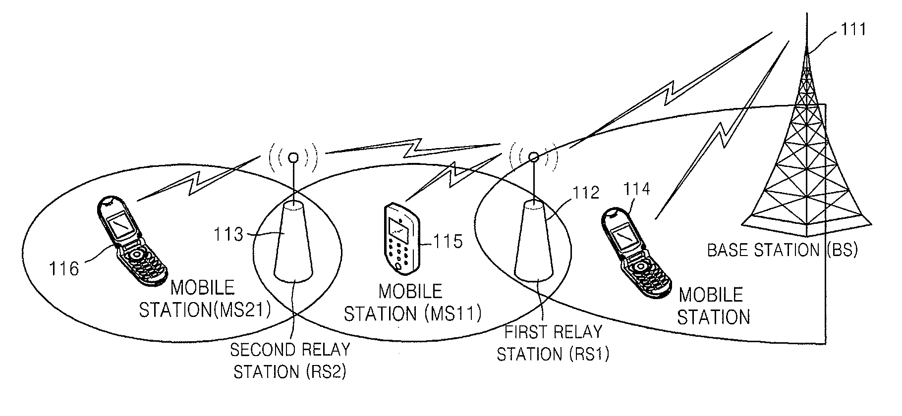
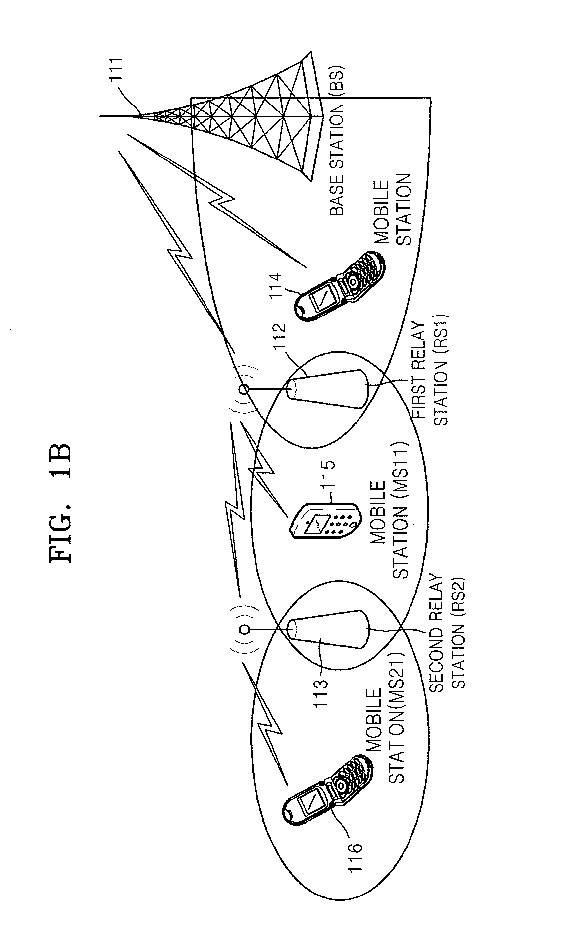
[0018]The present invention may be applicable to a multi-hop Mobile Multi-hop Relay (MMR) system, and may form a frame by which a first relay station receives a signal from a base station while simultaneously receiving a signal from a second relay station, and the first relay station transmits a signal to the base station while simultaneously transmitting a signal to the second relay station.

[0019]A structure of an MMR frame according to the present invention may simplify an implementation of a relay station, and may be applicable to not only a two-hop MMR system but also the multi-hop MMR system.

[0020]Hereinafter, a method of transmitting and receiving data in an MMR system, and a frame for the method will now be described more fully with reference to the accompanying drawings, in which exemplary embodiments of the invention are shown.

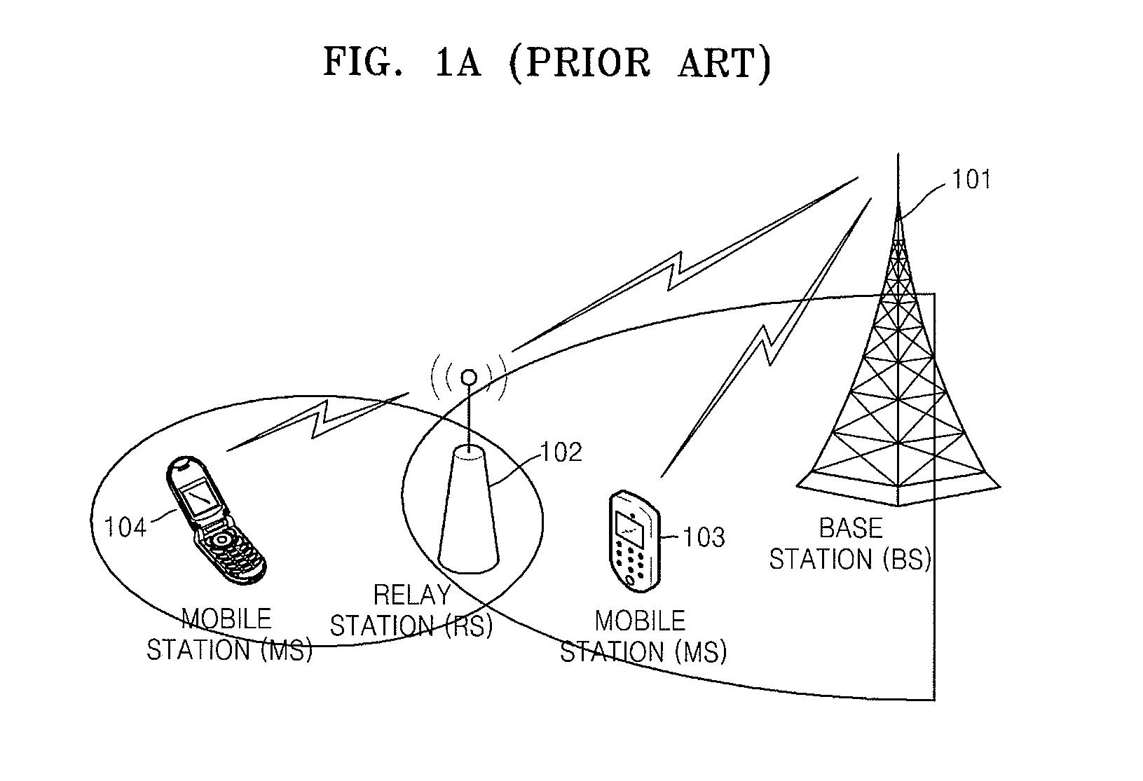
[0021]FIG. 1A is a diagram illustrating a two-hop MMR system, and FIG. 1B is a diagram illustrating a multi-hop MMR system.

[0022]FIG. 1A illustrates ...


PUM


Abstract

A method of forming a frame in a Mobile Multi-hop Relay (MMR) system, and a system for implementing the method are provided. In a multi-hop relay system, when a relay station of a specific layer receives data, the relay station receives data from both a higher layer and a lower layer. When the relay station transmits data, the relay station transmits data to both the higher layer and the lower layer. By doing so, data reception and data transmission are exclusively performed without interfering with each other, and the method and the system are easily applied to the multi-hop MMR system.

Description

CROSS-REFERENCE TO RELATED PATENT APPLICATION[0001]This application claims the benefit of Korean Patent Application Nos. 10-2006-0111272, filed on Nov. 10, 2006, and 10-2007-0093813, filed on Sep. 14, 2007 in the Korean Intellectual Property Office, the disclosures of which are incorporated herein their entirety by reference.BACKGROUND OF THE INVENTION[0002]1. Field of the Invention[0003]The present invention relates to a framestructure of transmitting and receiving data in a Mobile Multi-hop Relay (MMR) system, and more particularly, to a method of forming the framestructure for transmitting and receiving data between a base station and a relay station, or between relay stations in a multi-hop MMR system including three or more hops.[0004]The present invention is derived from research which was supported by the ‘Information Technology (IT) Research and Development Program’ of the Ministry of Information and Communications (MIC) / the Institute for Information Technology Advancement (...

Claims


Application Information

Patent Timeline
Patent Type & Authority Applications(United States)
IPC IPC(8): H04B7/14
CPCH04B7/2606H04B7/155
Inventor KIM, KI SEOKLEE, SEOK JINKIM, YOUNG IL
Owner ELECTRONICS & TELECOMM RES INST
Learn More