
Method and a system for detecting and locating an adjustment error or a defect of a rotorcraft rotor

a technology of rotorcraft and adjustment error, applied in the field of manufacturing helicopters, can solve problems such as inability to detect and locate adjustment errors or defects of rotorcraft rotors, and achieve the effect of low variance and high classification ra

Active Publication Date: 2008-05-15
EUROCOPTER
View PDF8 Cites 17 Cited by
  • Summary
  • Abstract
  • Description
  • Claims
  • Application Information

AI Technical Summary

Benefits of technology

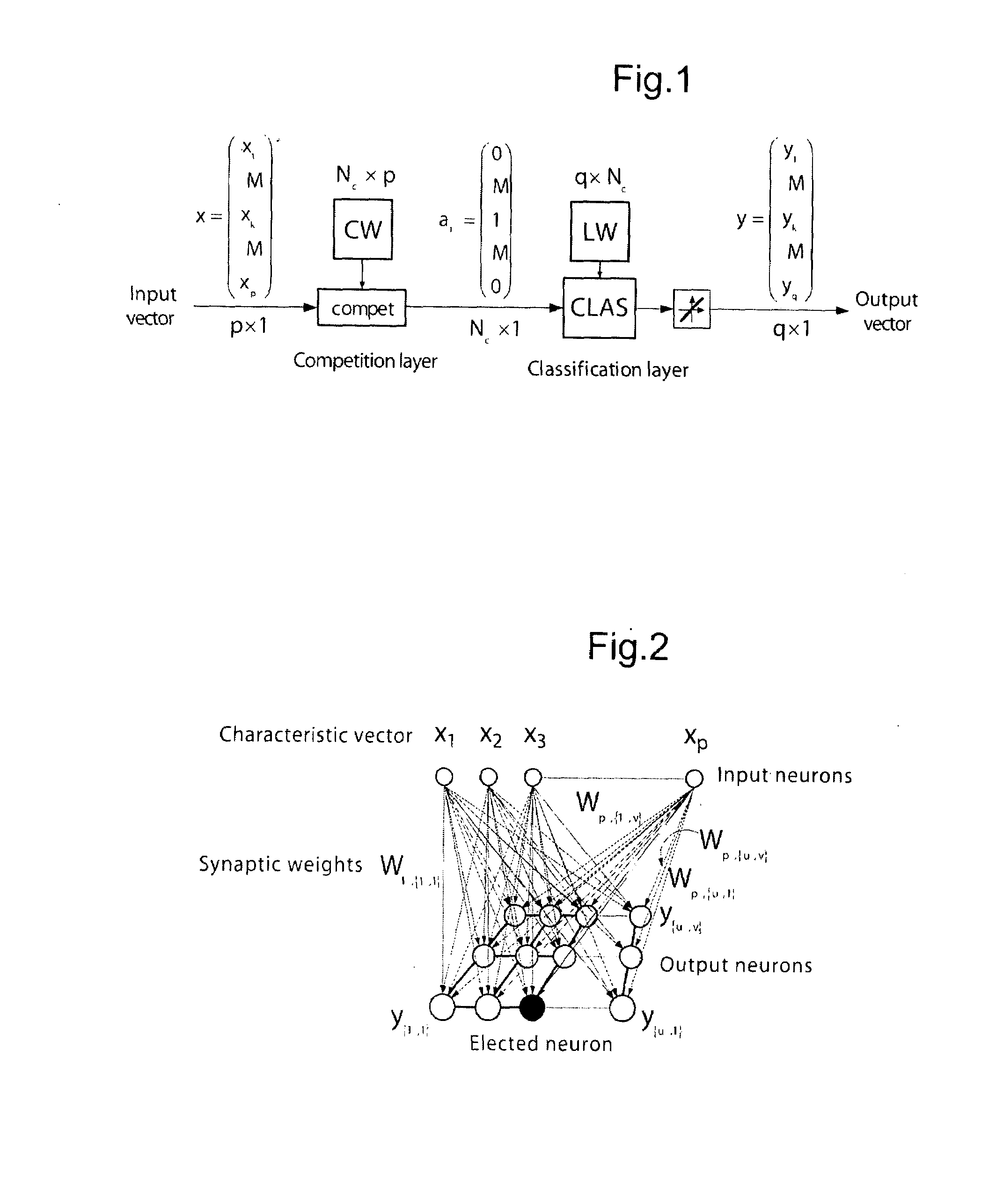
[0024]Competitive learning enables the algorithm to avoid converging on a “steady” state that does not correspond to a learning error minimum, and this is not possible with various other algorithms such as an error back-propagation algorithm.
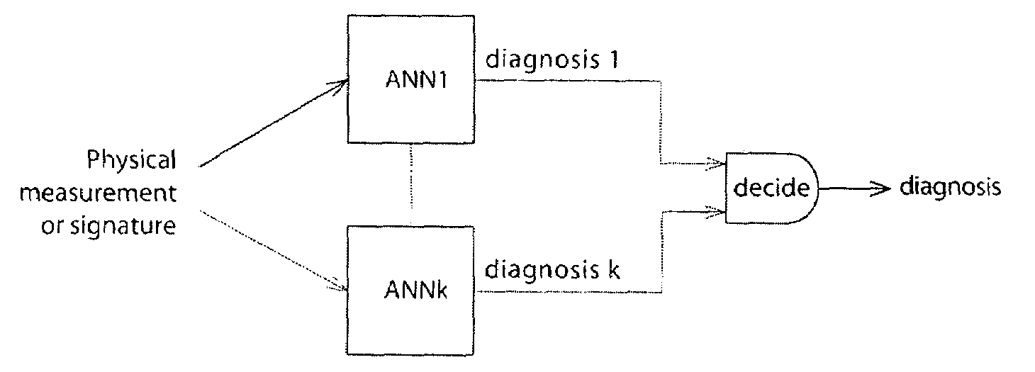
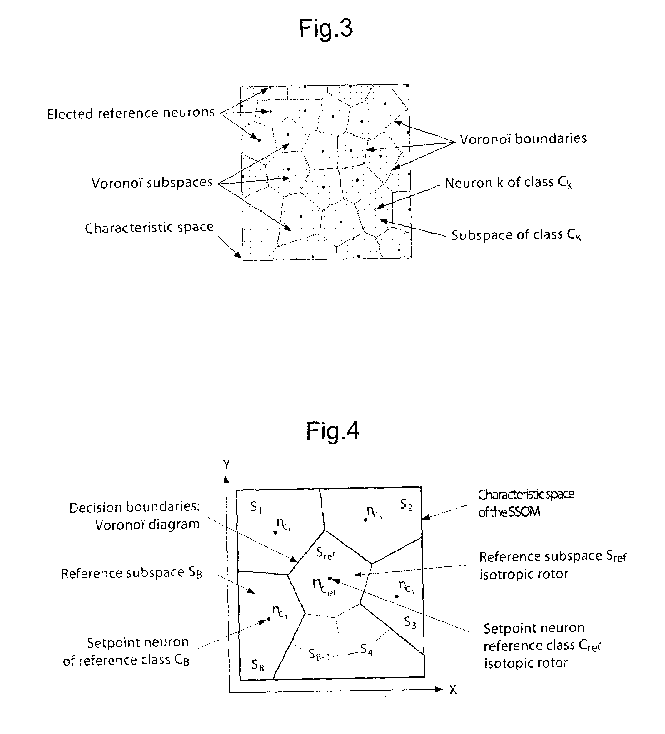
[0026]It has been found that an ANN with supervised competitive learning makes it easier to detect and distinguish defects and adjustment errors of a rotorcraft rotor on the basis of modulus and phase data concerning vibration measured on the rotorcraft.

Problems solved by technology

Competitive learning enables the algorithm to avoid converging on a “steady” state that does not correspond to a learning error minimum, and this is not possible with various other algorithms such as an error back-propagation algorithm.

Method used


Image

  • Method and a system for detecting and locating an adjustment error or a defect of a rotorcraft rotor
  • Method and a system for detecting and locating an adjustment error or a defect of a rotorcraft rotor
  • Method and a system for detecting and locating an adjustment error or a defect of a rotorcraft rotor

Examples


example 1

Classifying Signatures Measured on an AS365

[0145]The AS365 (Dauphin) is a 4-bladed helicopter. Measurements taken on an AS365 characterize the state of the out-of-adjustment rotor in two series of flights. On each flight, the adjustment errors, their points of application, and their magnitudes were different. A reference measurement (an in-adjustment rotor without any defect) was also taken.

[0146]The respective definitions of Ec relative to CB and CD were as follows:

Ec=CB⋃Cref=Cblade1⋃Cblade2⋃Cblade3⋃Cblade4⋃CrefEc=CD⋃Cref=dmass⋃drod⋃dtabs⋃Cref

[0147]The learning sample was constituted by the first series of flights. The second series constituted the sample to be classified. The parameters structuring the network and the learning were set at Niter=500, Nc=302, and σ0=3.

[0148]After learning relative to CB, it was found that the performance when classifying unlearned signatures was as follows: 90% of correct classification for an unsupervised SOM, and 100% correct classification for an...

example 2

Classifying Signatures Measured on an EC225

[0152]EC225 (Super Puma) is a 5-bladed helicopter. As in Example 1, measurements were taken during two series of flights (reference flight, flight with mass, rod, and tab adjustment errors), for errors of different amplitudes. The learning sample was constituted by the first series of flights, with the second series of flights constituting the classification sample.

[0153]The respective definitions of Ec relative to CB and CD were as follows:

Ec=CB⋃Cref=Cblade1⋃Cblade2⋃Cblade3⋃Cblade4⋃Cblade5⋃CrefEc=CD⋃Cref=dmass⋃drod⋃dtabs⋃Cref

[0154]Vibratory measurements were taken over a length of time sufficient to achieve convergence of acceleration amplitudes and phases. A Fourier transform was used to generate a plurality of vibratory signatures from each time signal. This example served to analyze the capacity of the SOM and of the SSOM to classify signatures calculated from signals at the limit of convergence. Two signature databases were used:[0155]...


PUM


Abstract

The invention relates to a method of detecting and identifying a defect or an adjustment error of a rotorcraft rotor using an artificial neural network (ANN), the rotor having a plurality of blades and a plurality of adjustment members associated with each blade; the network (ANN) is a supervised competitive learning network (SSON, SCLN, SSOM) having an input to which vibration spectral data measured on the rotorcraft is applied, the network outputting data representative of which rotor blade presents a defect or an adjustment error or data representative of no defect, and where appropriate data representative of the type of defect that has been detected.

Description

[0001]The present invention relates to a method and to a system for detecting and locating an adjustment error or a defect of a rotorcraft rotor.FIELD OF THE INVENTION[0002]The technical field of the invention is that of manufacturing helicopters.[0003]The present invention applies in particular to diagnosing a rotorcraft rotor by analyzing vibration that is generated, at least in part, by the operation of the rotor.BACKGROUND OF THE INVENTION[0004]In order to measure vibration, the rotorcraft is fitted with accelerometers that are placed (secured) on the casing(s) of the gearbox(es), on the bearings of shafts, and / or on other points of the structure of the helicopter.[0005]In flight, the signals delivered by these sensors can be converted into data, and where appropriate synchronized (by using signals delivered by a rotation sensor), and / or “averaged”, and then recorded by the imbedded system.[0006]On returning to the ground, the recorded data can be collated and analyzed. Interpre...

Claims


Application Information

Patent Timeline
Patent Type & Authority Applications(United States)
IPC IPC(8): G06F19/00G06F15/18
CPCB64C27/001G06K9/6272G05B23/024B64C27/008G06F18/24137
Inventor MOREL, HERVE
Owner EUROCOPTER
Learn More