
Cooling shade assembly and method of use thereof

a technology of shade assembly and cooling shade, which is applied in the direction of sunshades, door/window protective devices, transportation and packaging, etc., can solve the problems of reducing the performance of cool roof technology, reducing the efficiency of cooling roof technology, and reducing the efficiency of current energy systems. , to achieve the effect of reducing peak electricity load, and facilitating modification

Inactive Publication Date: 2008-05-22
FORBIS JACK R +1
View PDF11 Cites 35 Cited by
  • Summary
  • Abstract
  • Description
  • Claims
  • Application Information

AI Technical Summary

Benefits of technology

The shade assembly significantly reduces energy use, minimizes heat island effects, and provides economic benefits by blocking solar radiation, reducing the need for additional shading structures, and allowing for the use of natural light while maintaining easy access and aesthetic flexibility.

Problems solved by technology

A few types of shading panels have been developed to shade air conditioning units, but they are typically constructed of metal and / or fiberglass, and often stay hot due to the reradiation of heat on those panels.
Also, some coverings use materials that are not efficient at blocking or reflecting solar radiation.
However, insulation merely retards heat flow into the building from the exterior surfaces rather than preventing or reducing the heating of the exterior surfaces.
However, this technology affects only direct heat radiation entering a building through windows and fails to address the large amounts of heat absorbed by all exterior surfaces of a building.
These technologies can often be thwarted by peeling or cracking or other deterioration of the coating as well as by the accumulation of dirt on the coating which is difficult to remove and which reduces the performance of the cool roof technology.

Method used


Image

  • Cooling shade assembly and method of use thereof
  • Cooling shade assembly and method of use thereof
  • Cooling shade assembly and method of use thereof

Examples


Embodiment Construction

[0038] Specific embodiments of the present invention and their advantages are best understood by reference to FIGS. 1 through 6, where like numbers are used to indicate like and corresponding features.

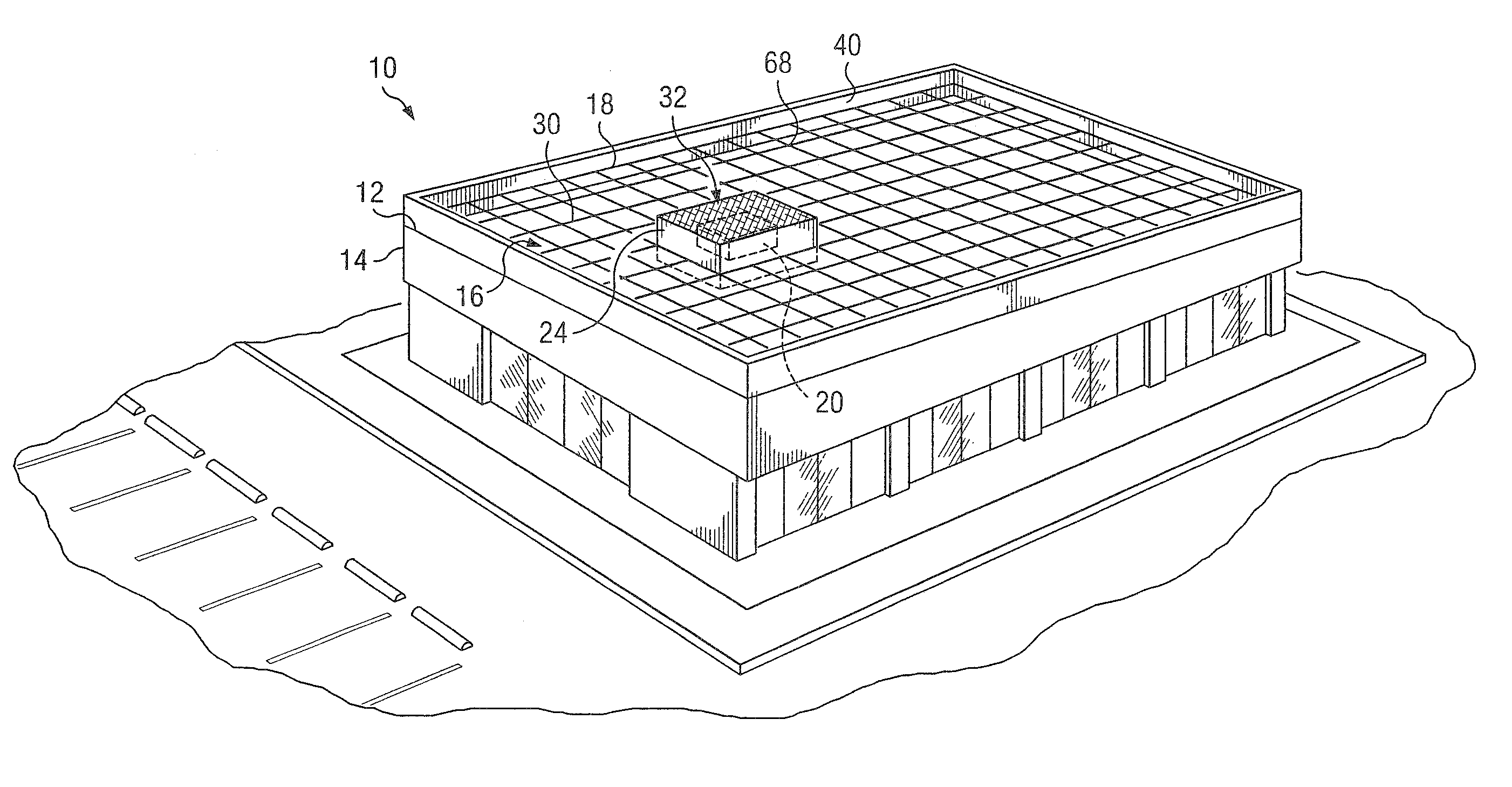
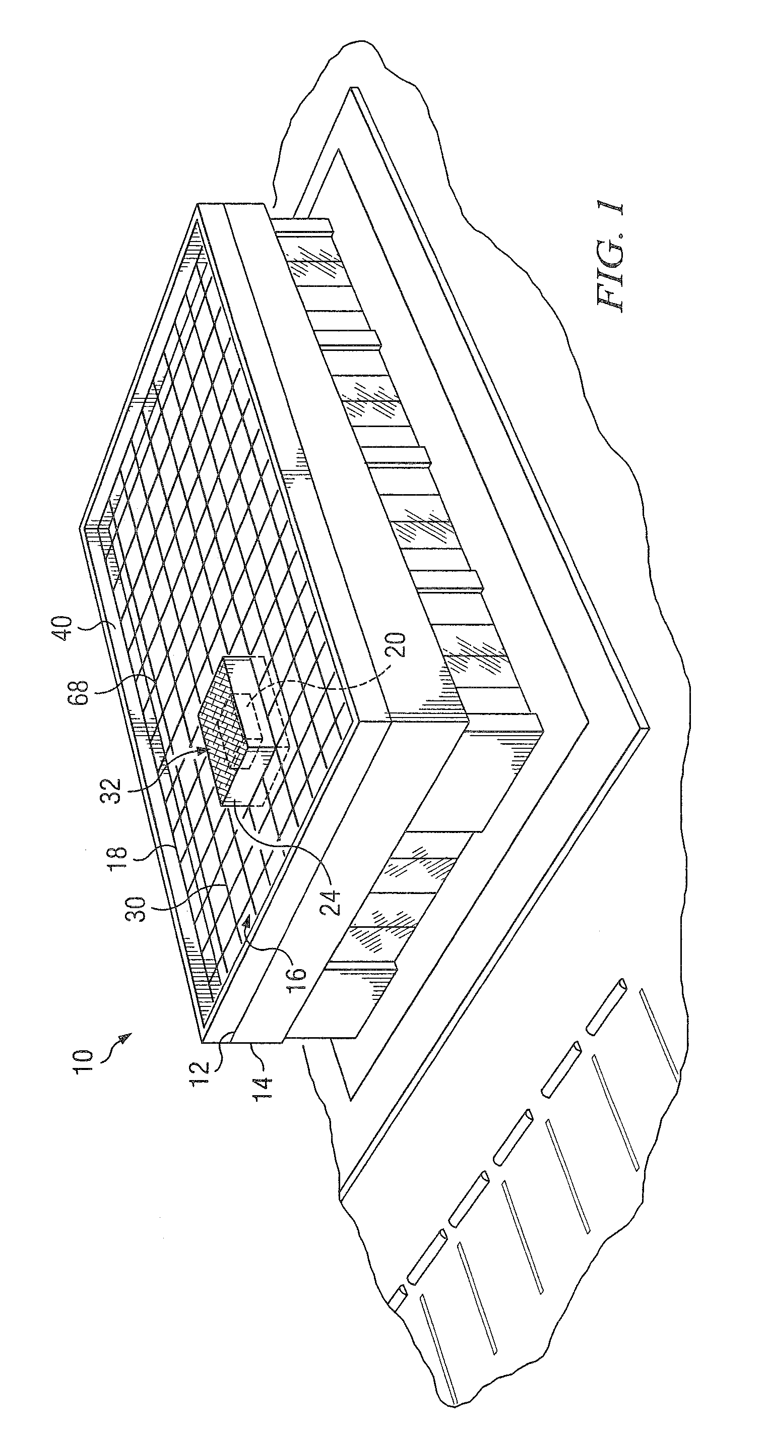
[0039] Referring to FIG. 1, roof shade assembly 10 is installed in an operative position overlying roof 12 of building 14 for the purpose of shielding roof 12 from solar radiation. Shade assembly 10 includes support assembly 68 formed from cables 30 attached to parapet wall 40 with anchors 18. Reflective shade panels 16 are fastened to cables 30 with fasteners such that panels 16 are in an operative, solar shielding position overlying and spaced above roof 12. Shade assembly 10 also includes shade box 32 with raised upright support posts 24 and dark or reflective shade panels attached thereto. Shade box 32 covers rooftop fixture 20.

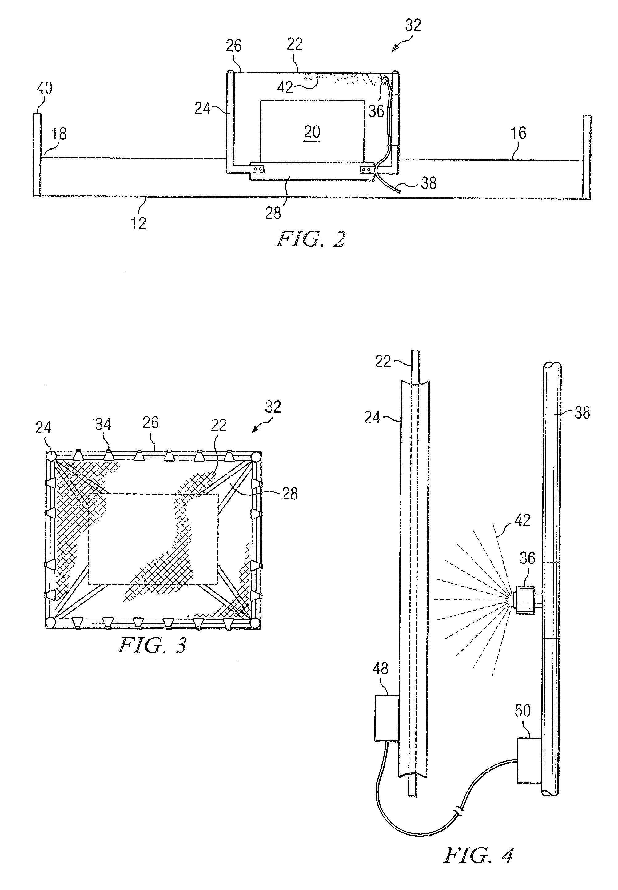
[0040] Referring to FIG. 2, reflective shade panels 16 are positioned at an operative level above roof 12 and are fastened to cables 30 which are attached...


PUM


Abstract

A shade assembly including reflective shade panels suspended above a roof or along an exterior wall of a building. The assembly also includes a shade box, such as one including an assembly of upright support posts and attached cables to which dark or reflective water-absorbent shade panels are attached. The shade box covers a rooftop fixture. The shade box can also include a water distribution system which dispenses water substantially onto the dark shade panels when they are included in the shade box. The shade assembly may also be used in a method for cooling the exterior surface of a building. The shade assembly may be used in a method of obtaining government economic incentives for energy efficiency such as emission reduction credits. A shade assembly including reflective shade panels suspended above a structure on or near the ground, such as a parking lot.

Description

CROSS REFERENCE TO RELATED APPLICATIONS [0001] This application is a continuation of U.S. Ser. No. 11 / 317,151, filed Dec. 23, 2005, which is a continuation of U.S. Ser. No. 10 / 393,619, filed Mar. 21, 2003, which claims priority under 35 U.S.C. § 119(e) to U.S. Provisional Patent Application No. 60 / 366,226, filed Mar. 21, 2002, the contents of which are hereby incorporated herein by reference in their entirety.STATEMENT REGARDING FEDERALLY SPONSORED RESEARCH OR DEVELOPMENT [0002] Not applicable. TECHNICAL FIELD OF THE INVENTION [0003] The present invention relates to a shade assembly and in particular a shade assembly for the exterior surface of a building and adjacent areas or parking lots and methods of use thereof. BACKGROUND OF THE INVENTION [0004] Heat, a form of kinetic energy, is generally transferred in three ways: conduction, convection and radiation. The transfer of heat energy by radiation makes possible the transfer of large amounts of heat from the sun to the earth. Radi...

Claims


Application Information

Patent Timeline
Patent Type & Authority Applications(United States)
IPC IPC(8): E04F10/00E04B1/74A01G27/00E04D13/00E04F10/08
CPCE04D13/00E04F10/08E04F10/00
Inventor FORBIS, JACK R.FORBIS, ANN R.
Owner FORBIS JACK R
Learn More