Method for thermal cutting

a cutting method and thermal cutting technology, applied in the field of thermal cutting, can solve problems such as irregular clocking, and achieve the effects of neat cutting edges, good quality and special cutting process

Inactive Publication Date: 2008-05-22
LINDE AG
View PDF2 Cites 7 Cited by
  • Summary
  • Abstract
  • Description
  • Claims
  • Application Information

AI Technical Summary

Benefits of technology

[0022]Both the method for thermal cutting according to the type explained above and the device for the thermal cutting according to the type explained above off

Problems solved by technology

However the clock

Method used


Image

  • Method for thermal cutting
  • Method for thermal cutting

Examples


Embodiment Construction

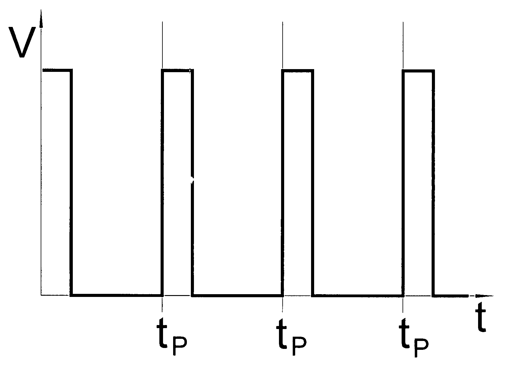
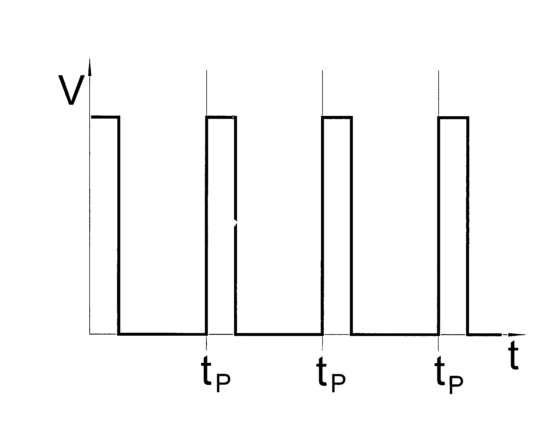
[0024]For quick and burr-free flame cutting with flame or laser beam oxygen with a high purity is preferentially employed. With the flame cutting methods an advantage in addition to the advantages in terms of driving-out of slag and melted material is obtained. Here, the cutting groove can cool down during the cutting process since, because of the absence of the cutting gas, burning of the oxygen is reduced. This improves quality and appearance of the cut groove since the undesirable oxidation layer on the cut edges is reduced. The risk of thermal distortion is also reduced and the amount of slag diminishes. Despite the reduction of the oxygen rate however this is adequate for introducing sufficient energy via the burning so that very fast cutting is possible.

[0025]With laser melt cutting the driving-out process of the melted material is of major importance so that the advantages according to the invention manifest themselves. With laser sublimation cutting the material at the place...


PUM

PropertyMeasurementUnit
Frequencyaaaaaaaaaa
Frequencyaaaaaaaaaa
Frequencyaaaaaaaaaa

Abstract

The invention relates to a method for thermal cutting, wherein a cutting gas is piped into a cutting nozzle and guided on to a work piece to be processed by means of the cutting nozzle. According to the invention the cutting gas is at least reduced in a periodically repetitive manner wherein the time in which the cutting gas is guided onto the work piece in an undiminished manner is shorter than half of a period. In addition the invention relates to a corresponding device with a valve.

Description

BACKGROUND OF THE INVENTION[0001]The present invention relates to a method for thermal cutting, wherein a cutting gas is piped into a cutting nozzle and by means of the cutting nozzle is guided to a work piece to be processed. In addition, the invention relates to a device for thermal cutting comprising a cutting gas supply pipe leading to a cutting gas nozzle and a valve provided in the cutting gas supply pipe.[0002]During thermal cutting work pieces are cut in that energy is supplied to the place to be cut, through which material at the processing location is removed and this material is finally driven out with the help of a gas jet, the so-called cutting jet. Of advantage here is that the tool, the cutting jet, does not become blunt and that hardly any force is exerted on the work piece to be cut. There are different possibilities of energy supply so that several thermal cutting methods exist.[0003]With flame cutting the material is heated to ignition temperature with a fuel gas-...

Claims


Application Information

Patent Timeline
IPC IPC(8): B23K9/013B23K10/00B23K7/00
CPCB23K7/00B23K26/38B23K10/00B23K9/013
Inventor DANZER, WOLFGANG
Owner LINDE AG
Why Eureka
Try Eureka