Pneumatic tire

a technology of pneumatic tires and tires, applied in the field of pneumatic tires, can solve the problems of uneven wear of land portions, excessive collapse of land portions, and small edge effect, and achieve the effects of suppressing the generation of cracks, preventing local stress concentration, and suppressing irregular wear

Active Publication Date: 2008-05-22
TOYO TIRE & RUBBER CO LTD
View PDF7 Cites 8 Cited by
  • Summary
  • Abstract
  • Description
  • Claims
  • Application Information

AI Technical Summary

Benefits of technology

[0021]In the above structure, it is preferable that at least one of the first concave and convex row and the second concave and convex row extends in the normal direction of the tread surface. In the case that the first concave and convex row extends in the normal direction of the tread surface, since the concave and convex row extending in the diagonal direction is not exposed to the tread surface in the wear initial state in which the land portion tends to comparatively collapse, it is possible to suppress the generation of a irregular wear without forming an acute portion in the land portion piece. On the other hand, in the case that the second concave and convex row extends in the normal dir

Problems solved by technology

In recent years, the number of the sipes tends to be increased for increasing an edge effect, however, if the number of the sipes is increased too much, a rigidity of the land portion is lowered and the land portion collapses excessively in spite that the number of the edges is increased.
Then there is generated a problem that the edge effect becomes small, whereby an ice performance is lowered,

Method used


Image

  • Pneumatic tire
  • Pneumatic tire
  • Pneumatic tire

Examples


example 1

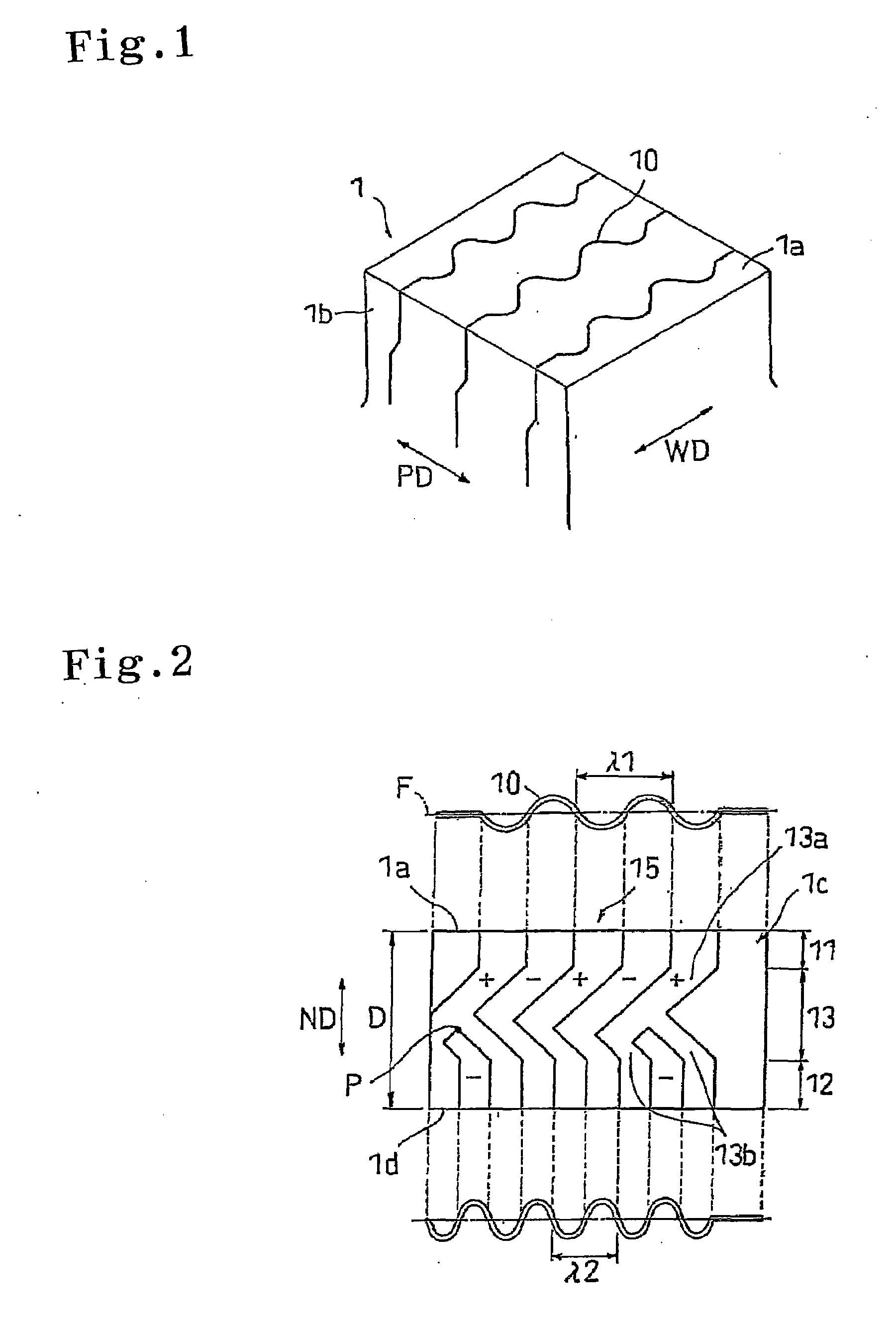
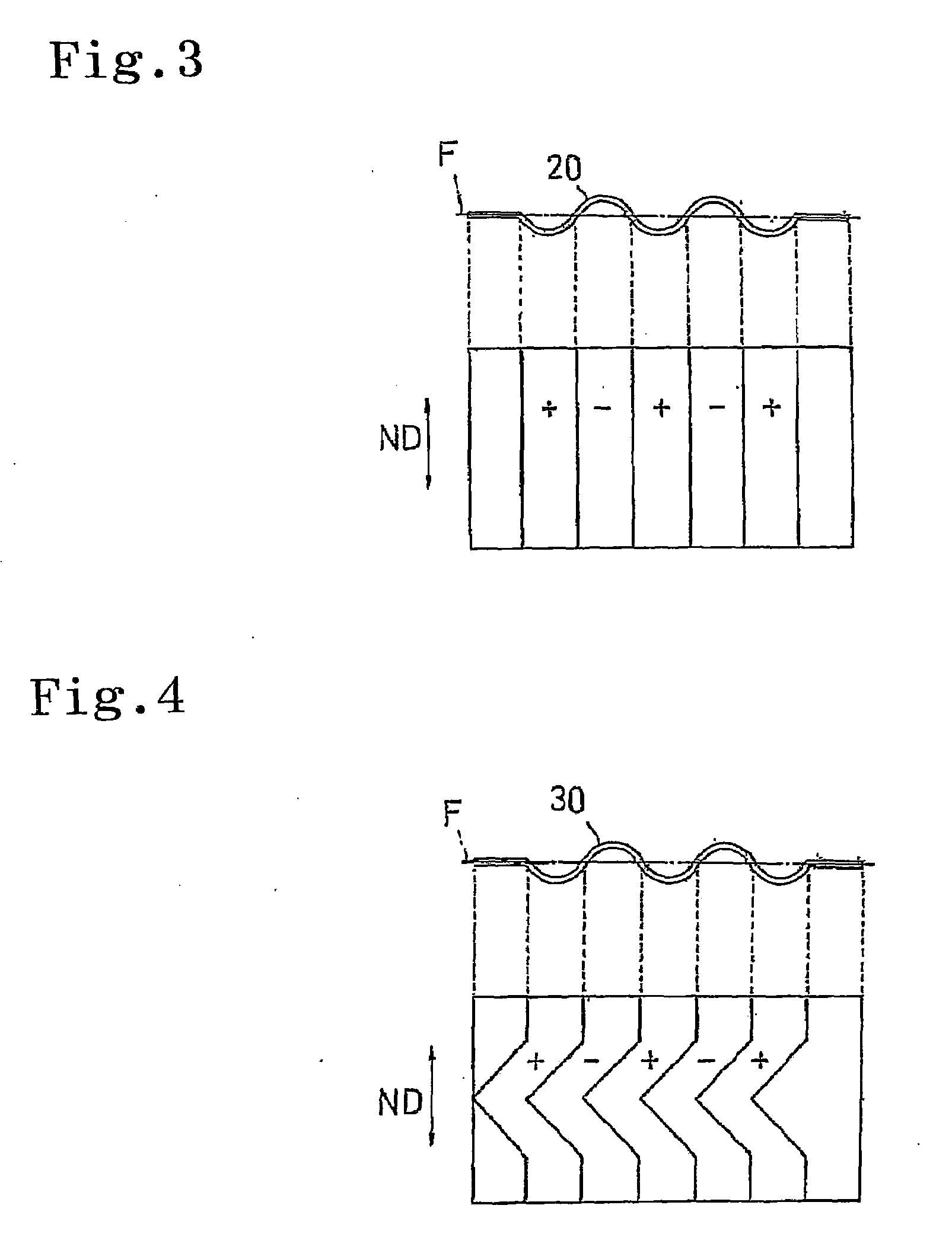
[0070]A radial tire having the same specification as the comparative example 1 except a structure in which the sipe shown in FIG. 2 is provided in place of the sipe shown in FIG. 3 is set to an example 1. In this case, a wavelength of the first concave and convex row is set to 4.0 mm, a wavelength of the second concave and convex row is set to 3.0 mm, each of angles of inclination of the main stem portion and the branch portion of the third concave and convex row with respect to the normal direction of the tread surface is set to 45 degree, and a branch point is set to a position at 0.4 D from the tread surface. Results of the evaluation are shown in Table 1.

TABLE 1ComparativeComparativeExample 1Example 2Example 1Ice braking100107111performanceWear100107110performanceWet braking100107109performance

[0071]In the result of evaluation, each of the performances (the ice braking performance, the wear performance and the wet braking performance) is improved in the comparative example 2 in ...


PUM


Abstract

A sipe inner wall surface of a sipe is provided with a wavy first concave and convex row, a wavy second concave and convex row arranged in a sipe bottom side from the first concave and convex row so as to be spaced, and structured such that a wavelength is made shorter than the first concave and convex row so as to increase the number of waves, and a third concave and convex row extending toward the sipe bottom side in a branched manner while being inclined to a longitudinal direction side of the sipe with respect to a normal direction of a tread surface, and interposed between the first concave and convex row and the second concave and convex row so as to be connected to both elements.

Description

BACKGROUND OF THE INVENTION[0001]1. Field of the Invention[0002]The present invention relates to a pneumatic tire provided with a tread pattern having a land portion in which at least one sipe is formed, and is particularly useful as a studless tire.[0003]2. Description of the Related Art[0004]Conventionally, in a studless tire, a cut called a sipe is provided in a land portion of a block, a rib or the like, and a stable travel can be achieved on an ice road surface having a low wear coefficient on the basis of an edge effect generated by the sipe. As the sipe mentioned above, there has been known a so-called two-dimensional sipe in which a shape is not changed in a depth direction, and there is put for practical use a flat sipe in which a sipe inner wall surface is flat, and a waveform sipe 20 in which concave and convex rows extend in a normal direction ND of a tread surface as shown in FIG. 3.[0005]In recent years, the number of the sipes tends to be increased for increasing an e...

Claims


Application Information

Patent Timeline
IPC IPC(8): B60C11/03
CPCB60C11/12B60C2011/1213B60C11/1218Y10S152/03
Inventor OHASHI, TOSHIYUKISATOU, SHOUTANUMATA, TAKASHI
Owner TOYO TIRE & RUBBER CO LTD
Why Eureka
Try Eureka