Heat sink

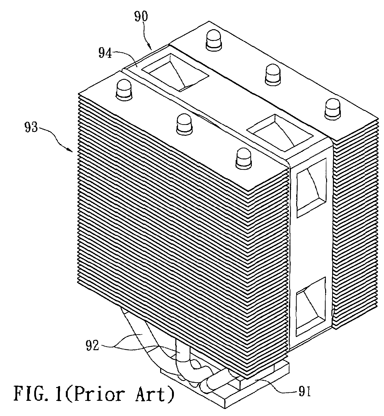
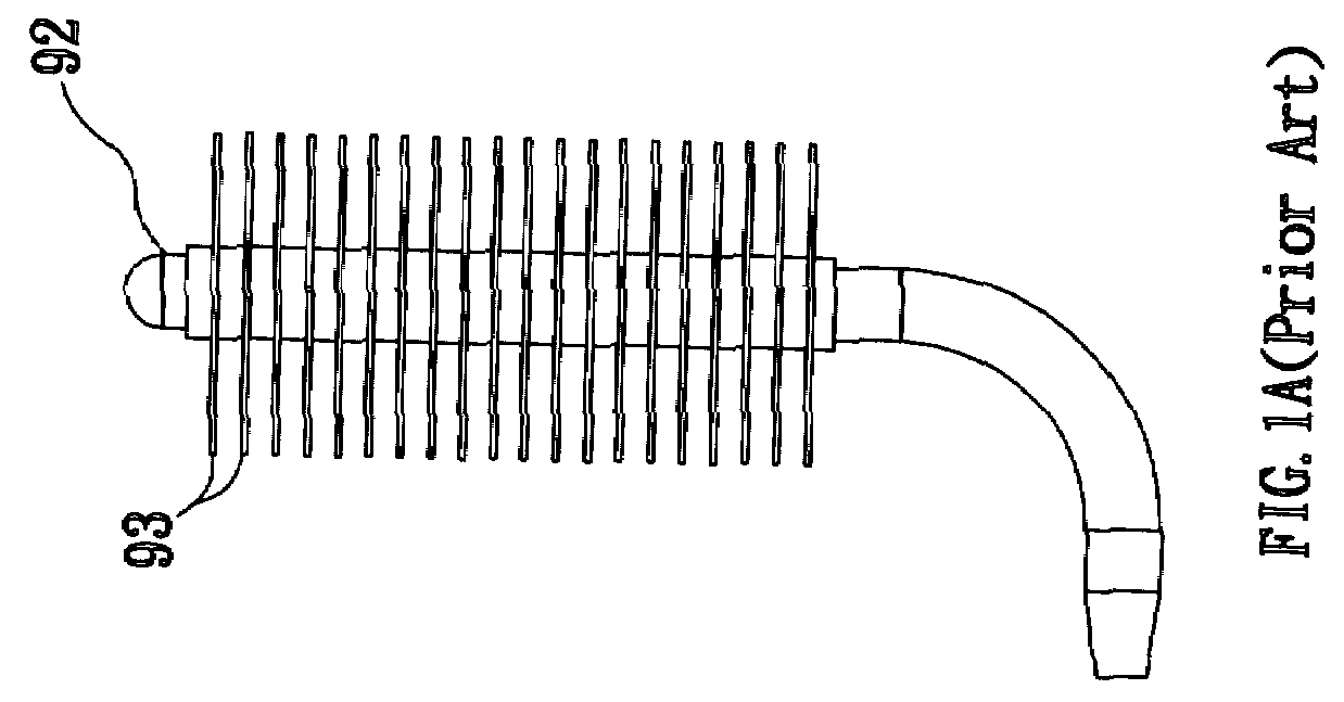
a heat sink and heat sink technology, applied in the field of heat sinks, can solve the problems of prolonging manufacture time, heat in the ambient area of the cpu cannot be effectively dissipated, and the heat sink b>90/b> cannot work efficiently in the overall ambient environment, so as to reduce manufacturing costs and simplify structure and manufacture.

Inactive Publication Date: 2008-05-22
COMPTAKE TECH
View PDF12 Cites 13 Cited by
  • Summary
  • Abstract
  • Description
  • Claims
  • Application Information

AI Technical Summary

Benefits of technology

[0007]Another object of the present invention is to provide a heat sink which simplifies structure and manufacture, and therefore reduces manufacture cost.

Problems solved by technology

Correspondingly, heat in ambient area of CPU is not able to be dissipated effectively.
So the heat sink 90 can not work efficiently for the overall ambient environment.
Because of this, positioning and assembling of the fins 93 are rather troublesome, prolonging manufacture time and increasing cost, and therefore lowering marketing competence.

Method used


Image

  • Heat sink
  • Heat sink
  • Heat sink

Examples


Embodiment Construction

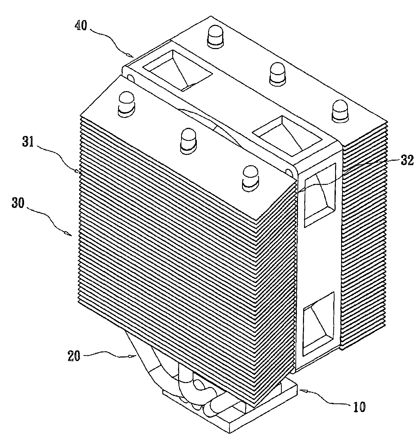
[0020]With reference to FIGS. 2 through 4, a heat sink in accordance with the present invention comprises a base 10, a plurality of heat pipes 20, a plurality of fins 30 and a fan 40. The base 10 is placed on a CPU (not shown) for absorbing heat generated by the CPU. Ends of the heat pipes 20 connect with the base 10. In other embodiments, another ends of the heat pipes 20 rewind and connect with the base 10.

[0021]The heat pipes 20 extend through and position the fins 30. The fins 30 form an inclined air surface 31 and a touching surface 32. The air surface 31 forms an inclined guiding angle α for heat absorption or dispersion. The fan 40 is provided on and joints the touching surface 32 for absorbing / dispersing heat from / toward the fins 30. The heat pipes 20 conduct and radiate the heat.

[0022]Referring to FIGS. 3A and 3B, the fins 30 form through holes 33 with a slant angle α, namely, the through holes 33 forms a slant angle α with regards to a longitudinal direction of the fins 30...


PUM


Abstract

A heat sink includes a base, at least a heat pipe connecting with the base, and a plurality of fins. The fins form through holes with a slant angle. The heat pipes extend through the through holes. The fins monolithically form an air surface with an inclined guiding angle for heat absorption or dispersion. The fins are assembled on the heat pipes such that the air surface of the fins forms an inclined angle for heat absorption or dispersion. The heat on ambient area around the CPU is effectively eliminated, promoting the whole effect of heat dissipation. The heat pipes are simply assembled, reducing manufacture cost and promoting marketing competence

Description

BACKGROUND OF THE INVENTION[0001]1. Field of the Invention[0002]The present invention relates to a heat sink, and particularly to a heat sink which has inclined dissipation angle for effectively dissipating heat and simplifying manufacturing.[0003]2. Related Art[0004]With development of electronic technology, IC tends to have high performance, and accordingly speed of CPU promotes quickly. Correspondingly, it is a more and more important issue to control and expel heat. So called 10 degree law means that life of IC would be cut down a half when temperature raises 10 degree. How to keep low temperature of IC is a key design of a heat sink, and decides lifespan of products with IC, especially in the event that speed of CPU promotes rapidly and heat density increases remarkably. In prior art, a fan and a fin are provided on a top of a CPU for dissipating heat. As shown in FIG. 1, a conventional heat sink 90 comprises a base 91, a plurality of heat pipes 92, fins 93 and a fan 94. The ba...

Claims


Application Information

Patent Timeline
Patent Type & Authority Applications(United States)
IPC IPC(8): H05K7/20
CPCH01L23/427H01L2924/0002H01L2924/00
Inventor CHEN, RYAN
Owner COMPTAKE TECH
Why Eureka
Try Eureka