
System for improved high frequency arc starting of a welding process

a high-frequency arc and welding process technology, applied in the direction of welding apparatus, manufacturing tools, welding/cutting media/materials, etc., can solve the problems of less reliable than contact starting systems, hf starting a tig welding process may fail on more than 25% of starts, and the reduction of the distance between the electrode and the workpi

Inactive Publication Date: 2008-05-22
ILLINOIS TOOL WORKS INC
View PDF12 Cites 9 Cited by
  • Summary
  • Abstract
  • Description
  • Claims
  • Application Information

AI Technical Summary

Benefits of technology

Enhances the reliability and consistency of high-frequency arc starting by increasing the probability of electron dislodgment within the nozzle assembly, reducing electrode wear and tungsten transfer, while being secure and compliant with safety standards.

Problems solved by technology

However, while HF starting systems serve to protect the electrode from the wear associated with shorting and breaking of a contact starting system, it is often less reliable than contact starting systems.
For example, it is not uncommon that HF starting a TIG welding process may fail on more than 25% of starts.
However, as the gap between the electrode and workpiece is decreased, the probability of the electrode contacting the workpiece increases.
Furthermore, in TIG welding processes, should the tungsten electrode strike the workpiece, some of the tungsten may be transferred to the workpiece and reduce the integrity of the weld.
Specifically, the system is insecure, unstable, and may be unintentionally separated or dismantled during normal welding operations.
That is, these systems are prone to inadvertently disassembly because the wire connecting the workpiece to the nozzle is merely clamped in place and dangling from the welding gun.
As such, the wire may be inadvertently removed from the clamp or may interfere with the welding process.
Furthermore, the clamp may obscure the operator’s view of the workpiece or interfere with the welding process.
Additionally, the clamp may be easily moved or dislodged from the nozzle during normal welding operations.
Also, the clamp securing the wire to the nozzle, while integral in creating the advantages of these piecemeal systems, is undesirable.
That is, the clamp is electrically charged and, therefore, creates a system that may not comply with applicable workplace standards and regulations.

Method used


Image

  • System for improved high frequency arc starting of a welding process
  • System for improved high frequency arc starting of a welding process
  • System for improved high frequency arc starting of a welding process

Examples


Embodiment Construction

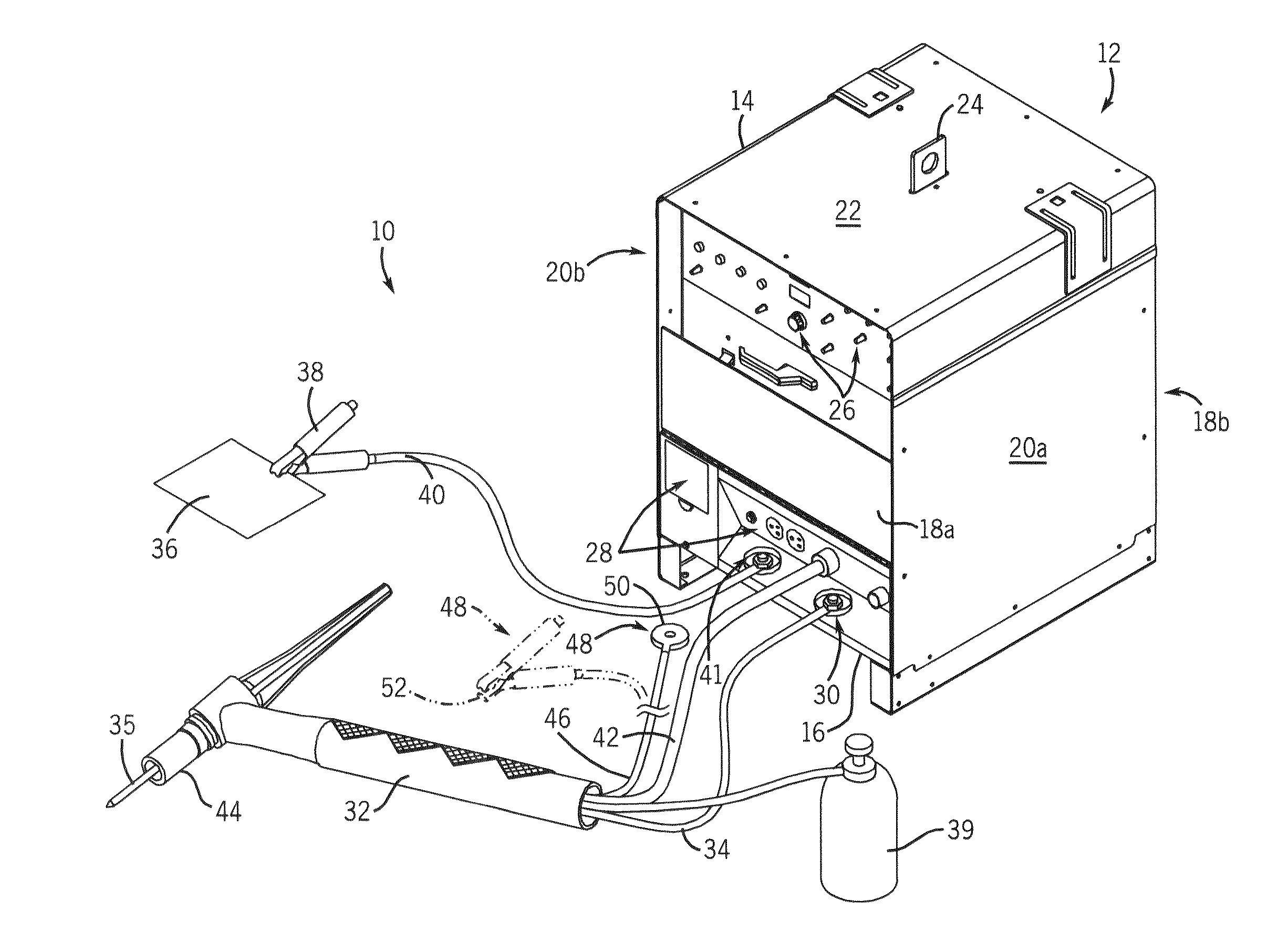
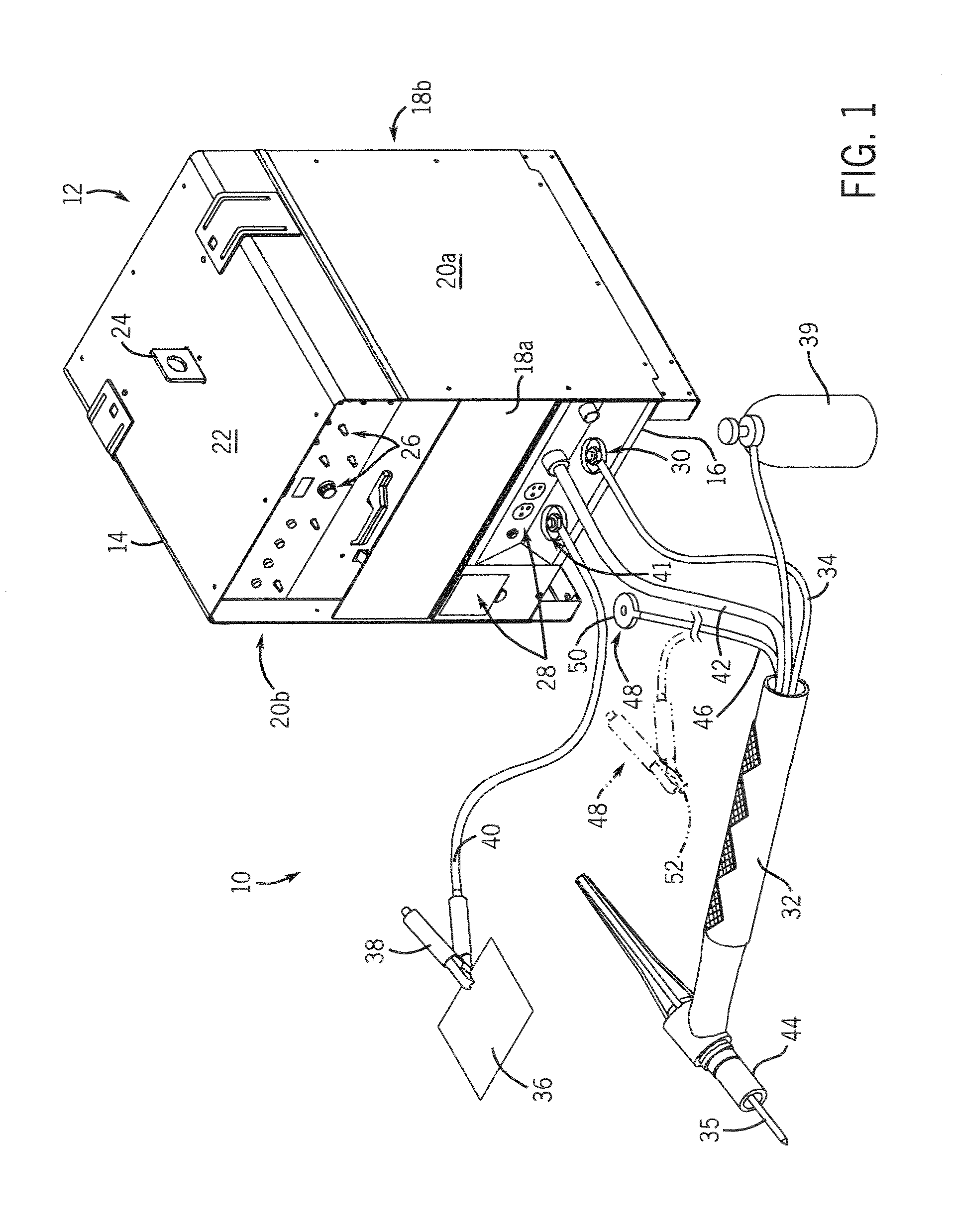
[0022]FIG. 1 is a perspective view of a welding-type system 10 suitable for a number of welding processes including tungsten inert gas (TIG) welding. The welding-type system 10 includes a power source 12 disposed within an enclosure 14. The power source 12 is constructed to condition raw power from a power supply into a power suitable for welding. Enclosure 14 is defined by a base 16, front and back panels 18a, 18b, and a pair of side panels 20a, 20b attached to the base 16. A top cover 22 having a handle 24 is secured to the pair of side panels 20a, 20b to form enclosure 14. The front panel includes control knobs 26 and outlets and receptacles 28 to facilitate connection of welding accessories to the power source 12. A welding gun output terminal 30 is used to connect a torch or gun 32 to the power source via cable 34. The gun 32 is designed to hold a tungsten electrode 35. To complete a welding circuit, a clamp 38 connects a workpiece 36 to the power source 12 via a cable 40 and w...


PUM


Abstract

A welding gun is disclosed that includes an electrode configured to effectuate a welding-type process and a non-conductive nozzle configured to at least partially surround the electrode. The welding gun also includes a conductive casing at least partially surrounding the nozzle and electrically isolated from the electrode and a conductive path extending from the conductive casing through the welding gun.

Description

CROSS-REFERENCE TO RELATED APPLICATION [0001] The present application is a continuation and claims priority of allowed U.S. Ser. No. 10 / 906,179 filed Feb. 7, 2005.BACKGROUND OF THE INVENTION [0002] The present invention relates generally to welding-type systems and, more particularly, to an apparatus for improved high-frequency arc starting of a welding process. [0003] There are a large number of welding processes available for use in industry. For example, some welding processes include gas tungsten arc, oxygen gas welding, and shielded metal arc welding. The gas tungsten arc welding process is generally referred to as tungsten inert gas (TIG) welding. A typical TIG welding apparatus includes a welding component which is commonly referred to as welding torch or gun and is designed to control a tungsten electrode during a welding process. That is, the welding gun holds the electrode which is heated to extremely high temperatures by electrical power received from the power source. At...

Claims


Application Information

Patent Timeline
Patent Type & Authority Applications(United States)
IPC IPC(8): B23K9/167B23K9/10B23K9/28
CPCB23K9/0673
Inventor HUTCHISON, RICHARD M.GADAMUS, JEFFERY J.
Owner ILLINOIS TOOL WORKS INC
Features
  • Generate Ideas
  • Intellectual Property
  • Life Sciences
  • Materials
  • Tech Scout
  • Unparalleled Data Quality
  • Higher Quality Content
  • 60% Fewer Hallucinations
Learn More