Gravity Gradiometer

a gravity gradiometer and gravity field technology, applied in the field of gravity gradiometers, can solve the problems of noise or swamp, oscillation of both sensor masses, and small oscillation ra

Active Publication Date: 2008-05-22
TECH RESOURCES PTY LTD
View PDF74 Cites 44 Cited by
  • Summary
  • Abstract
  • Description
  • Claims
  • Application Information

AI Technical Summary

Benefits of technology

[0023]The electronic circuit generates a voltage in response to an applied electrical input current and a feedback loop is established, which enables the simulation of the impedance in a manner such that low thermal noise is generated.
[0027]In one specific embodiment of the present invention the sensor and actuator unit is arranged for generating an ac electrical signal in response to an oscillation of the at least one sensor mass. In this embodiment the electronic circuit is arranged so that the imaginary component of the simulated impedance influences the resonance frequency of the at least one sensor mass via the actuator of the sensor and actuator unit. Consequently, selection of components of the electronic circuit, or tuning of the components, allows fine tuning of the resonance behaviour of the at least one sensor mass.
[0040]The electronic circuit generates a voltage in response to an applied electrical input current and a feedback loop is established, which enables the simulation of the impedance in a manner such that low thermal noise is generated.

Problems solved by technology

This creates accelerations of the gradiometer which are detected by the gravity gradiometer and if not compensated for, will produce noise or swamp actual accelerations or movement of the gradiometer in response to the gravity gradient which is to be detected by the gravity gradiometer.
For measurement of the gravity gradient the instrument is continuously rotated and a local change in the gravity gradient results in oscillating of both sensor masses relative to a rotated housing of the instrument.
The forces that result in such oscillation are very small and for proper operation of the gravity gradiometer each sensor mass should be balanced so that each sensor mass has the same dynamic properties, which provides a technological challenge.

Method used


Image

  • Gravity Gradiometer
  • Gravity Gradiometer
  • Gravity Gradiometer

Examples


Embodiment Construction

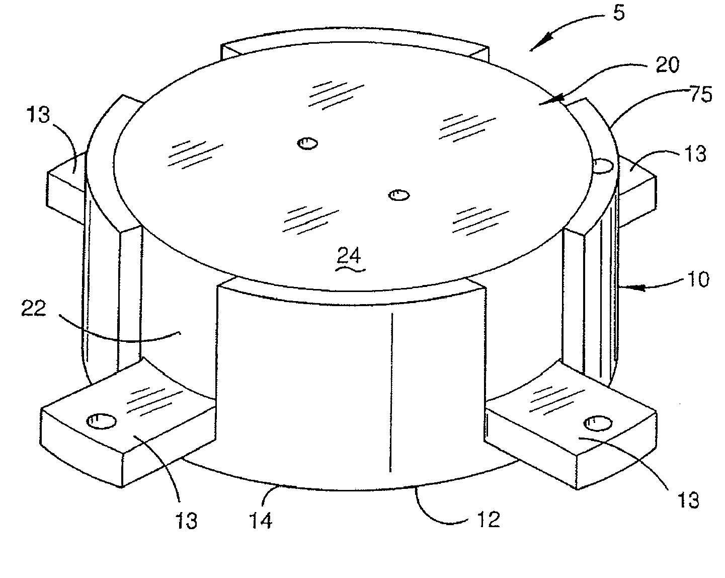
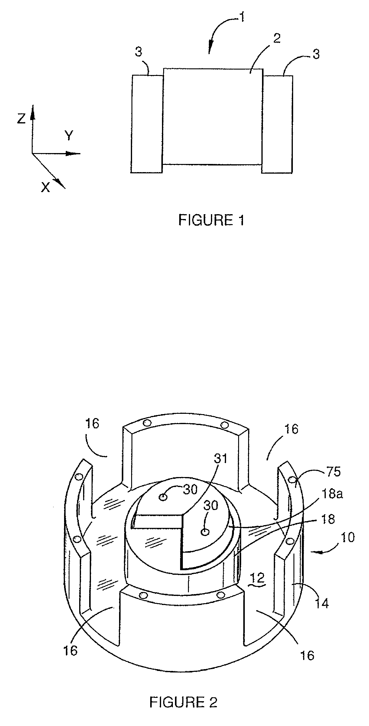
[0071]FIG. 1 is a schematic view of a gravity gradiometer 1 according to a specific embodiment of the present invention. The gravity gradiometer 1 is arranged for vertical positioning relative to a ground plane. Throughout this specification the ground plane coincides with an x-y plane of an x,y,z-coordination system and consequently the gravity gradiometer is in this embodiment arranged for orientation along the z-axis so that the Γxy and (Γxx-Γyy) components of the gravity gradient tensor can be measured.

[0072]The function of the gravity gradiometer 1 may be briefly summarised as follows. The gravity gradiometer has in this embodiment two substantially identical sensor masses which are pivotally mounted on a mounting so that they can oscillate relative to the mounting. The sensor masses with mounting are rotated about the z-axis and with an angular frequency that approximately equals half the resonance frequency of sensor masses. A gravity gradient will result in a force on the se...


PUM


Abstract

The present invention provides a gravity gradiometer for measuring components of the gravity gradient tensor. The gravity gradiometer comprises at least one sensor mass for movement in response to a gravity gradient and a sensor and actuator unit for generating an electrical signal in response to the movement of the at least one sensor mass and for influencing the movement of the at least one sensor mass. The gravity gradiometer also comprises an electronic circuit for simulating an impedance. The electrical circuit is arranged for amplifying the electrical signal received from the sensor and actuator unit and for directing an actuating signal to the sensor and actuator unit. The electronic circuit comprises a differential amplifiers having first and second amplifier input terminals and an amplifier output terminal and impedances Z1, Z2, Z3, at least one of the impedances have an imaginary impedance component.

Description

FIELD OF THE INVENTION [0001]The present invention relates to a gravity gradiometer and to components for high precision measurement instruments.BACKGROUND OF THE INVENTION [0002]Gravimeters are used in geological exploration to measure the first derivatives of the earth's gravitational field. Whilst some advances have been made in developing gravimeters which can measure the first derivatives of the earth's gravitational field because of the difficulty in distinguishing spatial variations of the field from temporal fluctuations of accelerations of a moving vehicle, these measurements can usually be made to sufficient precision for useful exploration only with land-based stationary instruments.[0003]Gravity gradiometers (as distinct from gravimeters) are used to measure the second derivative of the gravitational field and use a sensor which is required to measure the differences between gravitational forces down to one part in 1012 of normal gravity.[0004]Typically such devices have...

Claims


Application Information

Patent Timeline
Patent Type & Authority Applications(United States)
IPC IPC(8): G01V7/00G01R27/26
CPCG01V7/04
Inventor VAN KANN, FRANK JOACHIM
Owner TECH RESOURCES PTY LTD
Why Eureka
Try Eureka