
Structured asic layout architecture having tunnel wires

a layout architecture and structure technology, applied in the direction of logic circuits, pulse techniques, semiconductor devices, etc., can solve the problems of increasing the cost of masks in fabrication, increasing the cost of masks, and wasting considerable mask cost, so as to simplify the circuit connection scheme, improve the routability of chips, and save costs and routing resources

Inactive Publication Date: 2008-05-22
FARADAY TECH CORP
View PDF3 Cites 11 Cited by
  • Summary
  • Abstract
  • Description
  • Claims
  • Application Information

AI Technical Summary

Benefits of technology

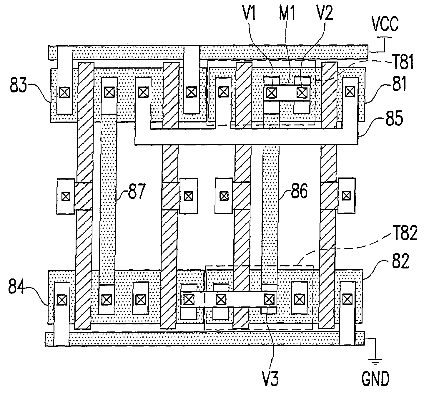
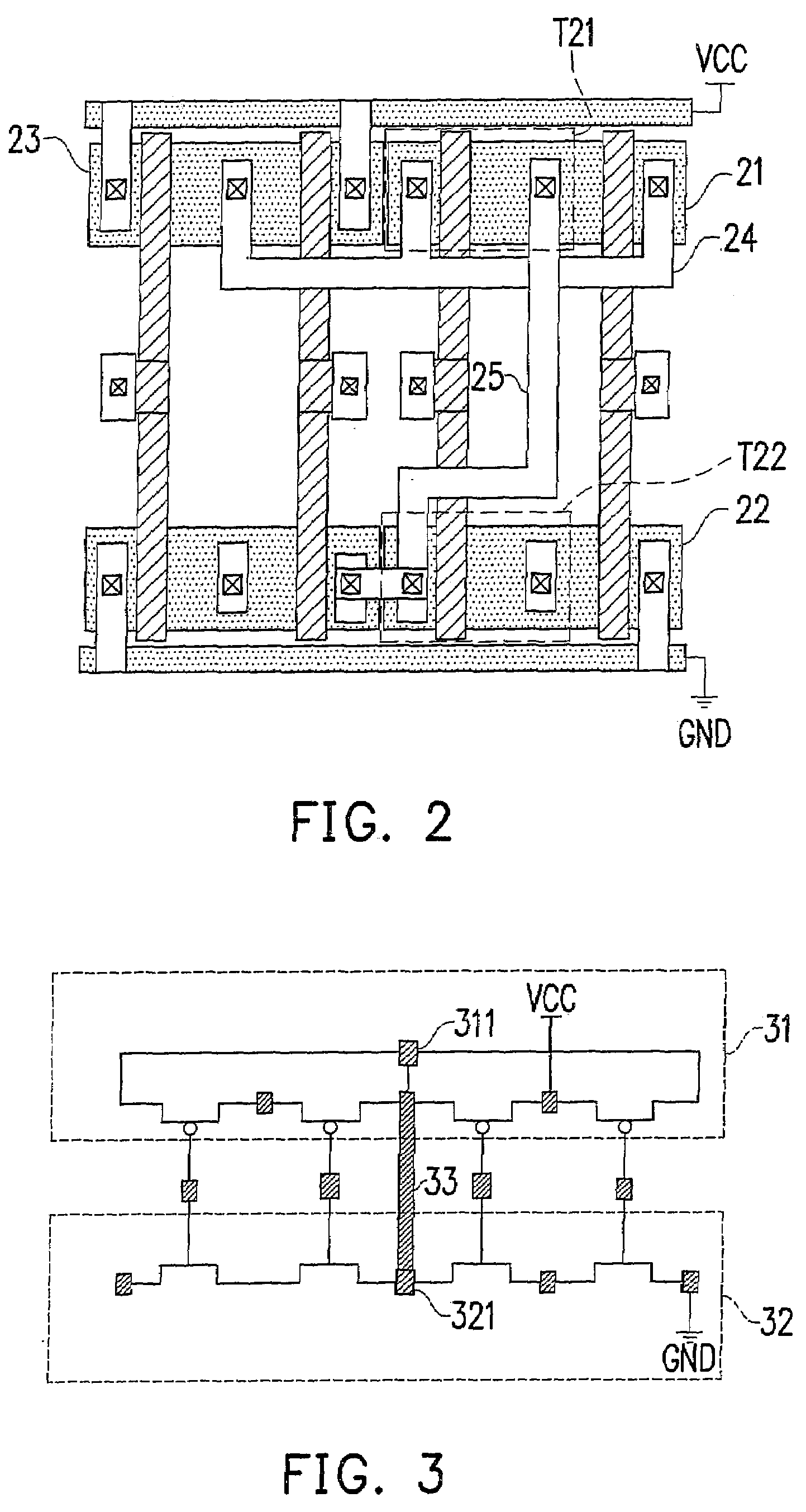
[0009]An objective of the present invention is to provide a structured ASIC layout architecture having tunnel wires, which is capable of saving cost, providing a simple circuit connection scheme, saving routing resource of the programmable layout region reserved for a customer's user end to tailor and improve the routability.
[0010]Another objective of the present invention is to provide a structured ASIC layout architecture having tunnel wires, which is capable of providing a simple circuit connection scheme for connecting multiple transistors to save cost, saving routing resource of the programmable layout region reserved for a customer's user end to tailor and improve the routability.
[0017]Since the present invention adopts a structure where the programmable layout region is adopted to propagate an electrical signal by using a tunnel wire of the fixed body region, and therefore it is possible to save cost and the routing resource of the programmable layout region reserved for a customer's user end to tailor, and simplify the circuit connection scheme and improve the routability in a chip.

Problems solved by technology

However, the cost of the mask correspondingly increases as the manufacturing process moves toward minimization day by day.
After a circuit has been designed, several steps of verification and modification are needed, which may require revision or improvement of the related hardware, resulting in an increase of the cost of the masks in the fabrication.
If the circuit design is improper, not only the cost of the masks is considerably wasted, but also the time on design is increased.
For chip design, the cost of the masks and various related designs is very high.
Thus, how to lower the R&D cost and shorten the development period is an important issue to cope with the nano-scale age.
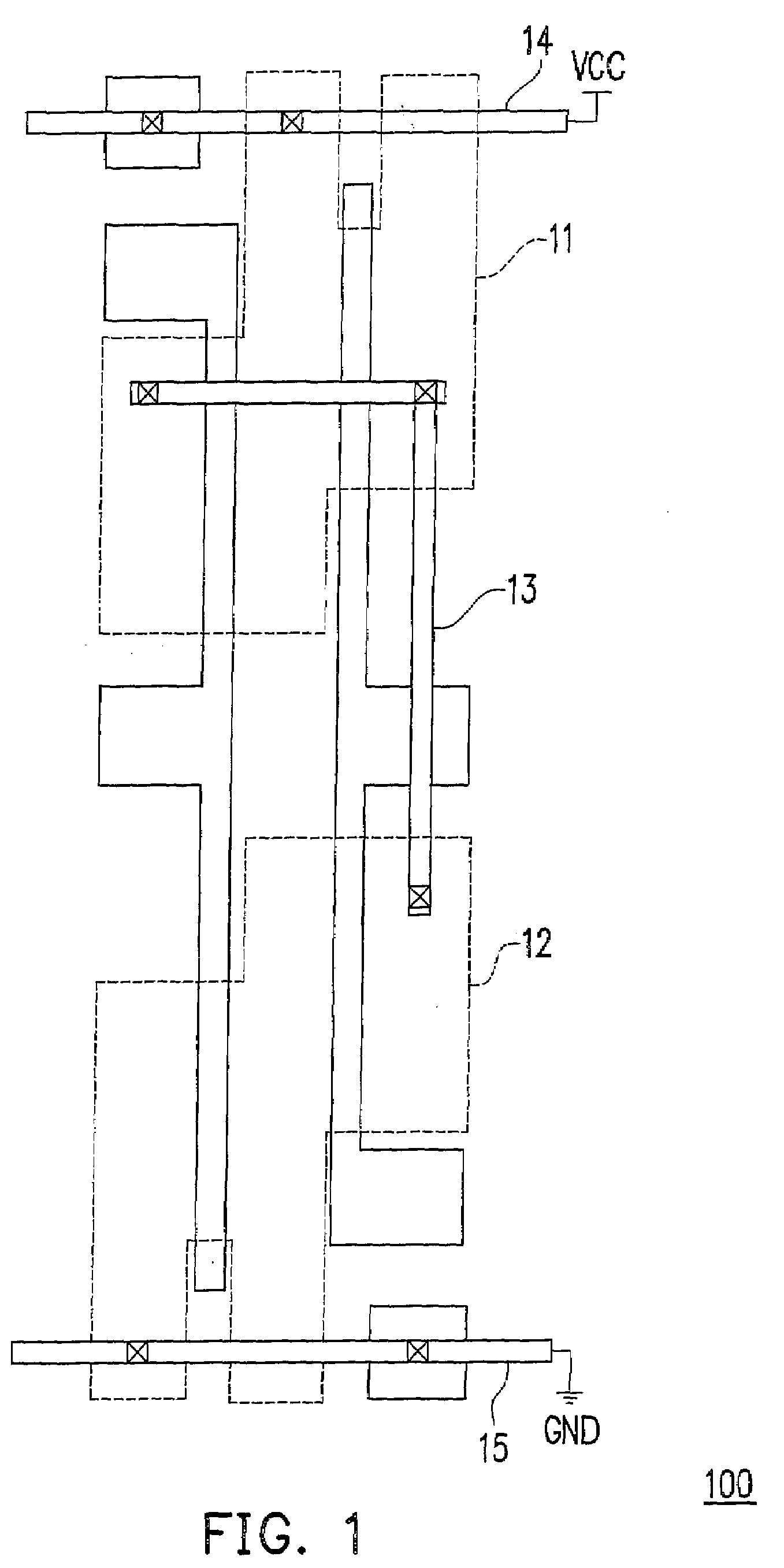
Even though the fixed connection manner is able to simplify the connection, but limits the functionalities and renders the design less flexible.

Method used


Image

  • Structured asic layout architecture having tunnel wires
  • Structured asic layout architecture having tunnel wires
  • Structured asic layout architecture having tunnel wires

Examples


Embodiment Construction

[0028]FIG. 4 is a schematic cross-sectional drawing of a structured ASIC layout architecture 400 according to an embodiment of the present invention, wherein structured ASIC layout architecture 400 includes tunnel wires and requires comparatively fewer number of masks for fabrication. The structured ASIC 400 includes a fixed body region 41 and a programmable layout region 42. The fixed body region 41 includes metal layers M41 and M42, via layers VIA41 and VIA42, a via contact layer CO41, a device region 412 and a substrate 411. The fixed body region 41 is, in association with the programmable layout region 42, used to provide a function capability or multiple function capability, such as the circuit operation or the phase-inverting signals. The device region 412 includes multiple circuit devices, such as P-type MOS transistors and P-type MOS transistors and is located on the substrate 411. The metal layer 41 is connected to the device region 412 through the via contact layer CO41, w...


PUM


Abstract

The present invention discloses a structured ASIC layout architecture, which includes a fixed body region and a programmable layout region. The fixed body region includes a tunnel wire or multiple tunnel wires for providing a function capability or multiple function capability. The programmable layout region is disposed on the fixed body region and is connected to the fixed body region, wherein the programmable layout region utilizes the tunnel wires of the fixed body region to propagate electrical signals.

Description

BACKGROUND OF THE INVENTION[0001]1. Field of the Invention[0002]The present invention relates to a structured ASIC layout architecture, and more particularly, to a structured ASIC layout architecture having tunnel wires.[0003]2. Description of the Related Art[0004]Along with the development of the nano-dimension scale in the semiconductor process and the complexity of the SoC (system on chip) technology in the circuit design, circuit design verification gradually becomes one of the key factors that will affect the schedule of R&D. In the circuit design, some steps such as trial chip verification, prototype fabrication and production yield forecast will be carried out first, so as to justify mask cost. However, the cost of the mask correspondingly increases as the manufacturing process moves toward minimization day by day. After a circuit has been designed, several steps of verification and modification are needed, which may require revision or improvement of the related hardware, re...

Claims


Application Information

Patent Timeline
Patent Type & Authority Applications(United States)
IPC IPC(8): H03K19/173H03K19/00
CPCH01L27/11807H01L27/0207
Inventor WU, CHANG-YUKU, MING-HSINHSIEH, SHANG-CHIHWANG, HSIN-SHIH
Owner FARADAY TECH CORP
Learn More