Temperature Fuse Protection Device

a technology of fuse protection and temperature control, which is applied in the manufacture of emergency protective devices, emergency protective devices, emergency protective circuit arrangements, etc., can solve the problems of device crashing or inability to operate normally, reducing the lifespan of usage, and sparks and thus dangers, so as to ensure the safety of electric usage, reduce the lifespan of electronic products, and the effect of stable operation

Inactive Publication Date: 2008-05-22
YU TSUNG MOU
View PDF24 Cites 23 Cited by
  • Summary
  • Abstract
  • Description
  • Claims
  • Application Information

AI Technical Summary

Benefits of technology

[0013]A primary objective of the present invention is to provide a temperature fuse protection device which overcomes the drawbacks of the traditional temperature sensing circuit breaker for individual electronic product that cannot set the reaction temperature value for the power cut-off accurately and effectively, and prevent the contact spring from bouncing back to connect the circuit again in various manner, thus leading to the unstable operation and lower lifespan of the electronic products, and as far as even complete destruction.
[0014]In accordance with an aspect of the present invention, there is provided a temperature fuse protection device which uses a hot melt metal to be riveted and connected onto two separated terminals of the circuit for making them electrically-connected. When no external force is imposed, the space between the two free ends of the two terminals remains to be a spacing. During an electric overload or high circuit temperature event, the hot melt metal will break, and the two free ends of the two terminals will thereby disconnect, and thus the circuit will be at “OFF” status. As a result, the electric usage safety is guaranteed.
[0015]Another objective of the present invention to use the characteristics of the hot melt metal for making certain to melt and break to make sure the circuit is completely at the “OFF” status without having to worry about the dangers of circuit temperature fluctuations or the contact spring from bouncing and deflecting back and forth contact to for connecting the circuit again and again. As a result, the electric usage safety is again guaranteed.
[0016]A further objective of the present invention is that the riveting method using a hot melt metal for connecting the two separated terminals of the circuit has the advantages of having a simpler structure, improved manufacturability, reduced volume, and cost efficiency.

Problems solved by technology

The repeated turning “ON” and “OFF” is easy to cause sparks and thus dangers.
Because of the repeated turning “ON” and “OFF” of the electrical power circuit, the electronic and electrical devices are to experience unstable electrical current, thus leading to device crashing or inability to operate normally, reduction of usage lifespan, and even possibly complete failure.

Method used


Image

  • Temperature Fuse Protection Device
  • Temperature Fuse Protection Device
  • Temperature Fuse Protection Device

Examples


first embodiment

[0034]Referring to the drawings, FIGS. 3 and 4 are an exploded cross-sectional view and an assembled cross-sectional view showing a first embodiment constructed in accordance with the present invention, respectively; FIG. 5 is an assembled cross-sectional view which shows the breaking of the hot melt metal during an electrical or high circuit temperature event, the separation of the free ends of the two terminals from each other, and the circuit at “OFF” status. The temperature fuse protection device in accordance with the present invention comprises two terminals 11, 12 and a hot melt metal 13. An attachment assembly for the two terminals 11, 12 are established in a circuit and the free ends of the two terminals 11, 12 between which is kept at a spacing ΔS1 when no external force is imposed are formed with a through hole 111, 121 respectively to pass through. The through holes can be closed or open structure and at least one terminal of the two is made of elastic electric-conducted...

second embodiment

[0043]Referring to FIG. 12, FIG. 12 is an assembled perspective view of the second embodiment in accordance with the present invention.

[0044]Referring to FIG. 11, FIG. 11 shows another shape of the hot melt metal 16 of the second embodiment, with one end having an enlarged cap shape, and the assembly mode is to the same as the hot melt metal 15 in FIG. 8.

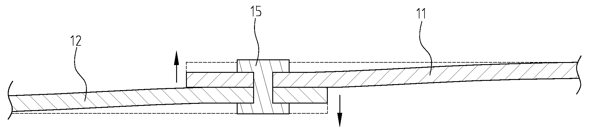
[0045]When electric overloading or high circuit temperature occurs, the hot melt metal 15 will melt and break when reached at the set temperature. The free ends of the two terminals 11, 12 relinquish their riveting force given by the hot melt metal 15, and are separated from each other because of the opposing force due to elasticity, whereby they will be disconnected; and the circuit will be at “OFF” status (shown in FIG. 10).

[0046]FIGS. 13-15 are an exploded perspective view, assembled perspective view, and assembled cross-sectional view, respectively, showing a third embodiment of the present invention; FIG. 16 is an assembled cro...

third embodiment

[0047]The temperature fuse protection device in accordance with the present invention comprises two terminals 11, 12, a hot melt metal 17, and an elastic connecting unit 18. The attachment assembly for the two terminals 11, 12 is established in a circuit, and at least one free end of the two terminals is formed with a through hole 121 to pass through. As for this embodiment, the through hole 121, which can be an open or closed structure, is disposed at the free end of the first terminal 12. The free end of the second terminal 11 is formed with an attachment piece 112, and between the two free ends of the two terminals 11, 12, a spacing ΔS4 is kept when no external force is imposed.

[0048]The hot melt metal 17 is strip-shaped, and has the characteristics of breaking when it is heated or at an elevated temperature. The hot melt metal 17 can have one end having an enlarged cap shape, and can change the composition according to requirements to allow for different hot melt metal breaking ...


PUM

PropertyMeasurementUnit
temperatureaaaaaaaaaa
elasticaaaaaaaaaa
elasticityaaaaaaaaaa

Abstract

A temperature fuse protection device uses a hot melt metal to rivet for connecting two terminals in the circuit that are separated for making the two terminals electrically-connected and the circuit complete. There is a spacing in between the two free ends of the two terminals when no external force is being imposed. When an electric overloading or high circuit temperature event occurs, the hot melt metal would be heated to melt and break, which would then make the free ends of the two terminals to be disconnected, and therefore, the circuit will be at “OFF” status.

Description

BACKGROUND OF THE INVENTION[0001]1. Field of the Invention[0002]The present invention relates generally to a temperature fuse protection device which uses a hot melt metal for rivet coupling two separate terminals in a circuit for making the two terminals to be electrically-connected to the circuit, whereby the hot melt metal will break under heating and elevated temperature, and the circuit will become at the “OFF” status.[0003]2. The Prior Arts[0004]Electricity has become a must in modern society, which has surrounded all our lives. IT industry, homes, transportation, education, entertainment, etc, are all heavily dependent on electricity. Therefore, the safe usage of electricity has become more and more vital for people.[0005]Generally speaking, the overall circuit is set with a main switch generally at the “ON” status in electric power plant. During an electrical overloading, short-circuiting, or high circuit temperature event, the fuse is melted or the circuit breaker is jumped...

Claims


Application Information

Patent Timeline
Patent Type & Authority Applications(United States)
IPC IPC(8): H01H37/76
CPCH01H37/761H01H85/04Y10T29/49107H01H2037/762H01H2037/763H01H85/36
Inventor YU, TSUNG-MOU
Owner YU TSUNG MOU
Why Eureka
Try Eureka