Eureka AIR delivers breakthrough ideas for toughest innovation challenges, trusted by R&D personnel around the world.

Diffusing member, light emission device with the diffusing member, display having the light emission device

Inactive Publication Date: 2008-05-22
SAMSUNG SDI CO LTD
View PDF7 Cites 0 Cited by
  • Summary
  • Abstract
  • Description
  • Claims
  • Application Information

AI Technical Summary

Benefits of technology

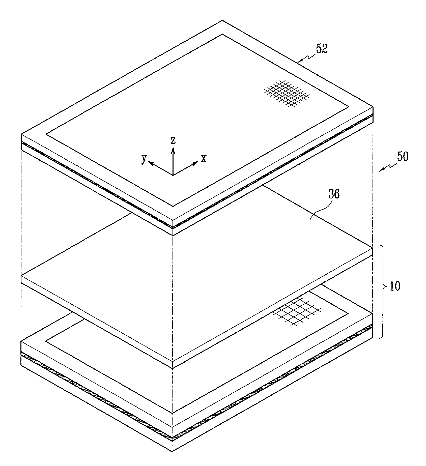
[0015]Aspects of exemplary embodiments of the present invention are directed to a light emission device including a diffusing member (or diffuser) having an improved (or optimal) light transmittance appropriate for a surface light source and a display that can reduce a light loss by employing the light emission device.
[0016]Other aspects of exemplary embodiments of the present invention are directed to a light emission device that has a light emission surface divided into a plurality of sections and that can independently control a light emission intensity of each section, and a display that can enhance a contrast ratio by employing the light emission device.
[0031]The diffuser plate may be adapted to protect the diffuser sheet from being folded and / or wrinkled.

Problems solved by technology

However, since the CCFL emits the light through the optical member, there may be some light loss.
Considering this light loss, the CCFL needs to consume a relatively large amount of power to emit a high intensity of light, thereby increasing the overall power consumption of the liquid crystal display employing the CCFL.
In addition, due to its structural limitation, it is difficult to enlarge the display employing the CCFL; i.e., it is difficult to apply CCFL to a liquid crystal display that is over 30 inches.
However, the LED is costly and increases an overall thickness of the liquid crystal display.
However, since the diffuser plate and diffusion sheet have a relatively low light transmittance and cause a light loss, the luminance of the backlight unit is deteriorated.
Therefore, it is difficult to improve the display quality to a sufficient level.

Method used


Image

  • Diffusing member, light emission device with the diffusing member, display having the light emission device
  • Diffusing member, light emission device with the diffusing member, display having the light emission device
  • Diffusing member, light emission device with the diffusing member, display having the light emission device

Examples


Embodiment Construction

[0039]In the following detailed description, only certain exemplary embodiments of the present invention are shown and described, by way of illustration. As those skilled in the art would recognize, the invention may be embodied in many different forms and should not be construed as being limited to the embodiments set forth herein. Also, in the context of the present application, when an element is referred to as being “on” another element, it can be directly on the another element or be indirectly on the another element with one or more intervening elements interposed therebetween. Like reference numerals designate like elements throughout the specification.

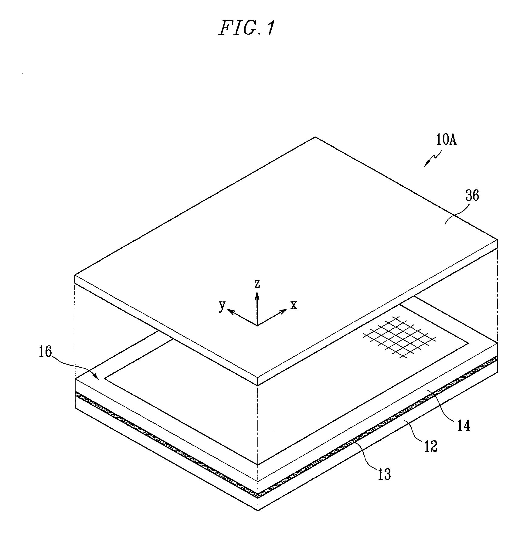
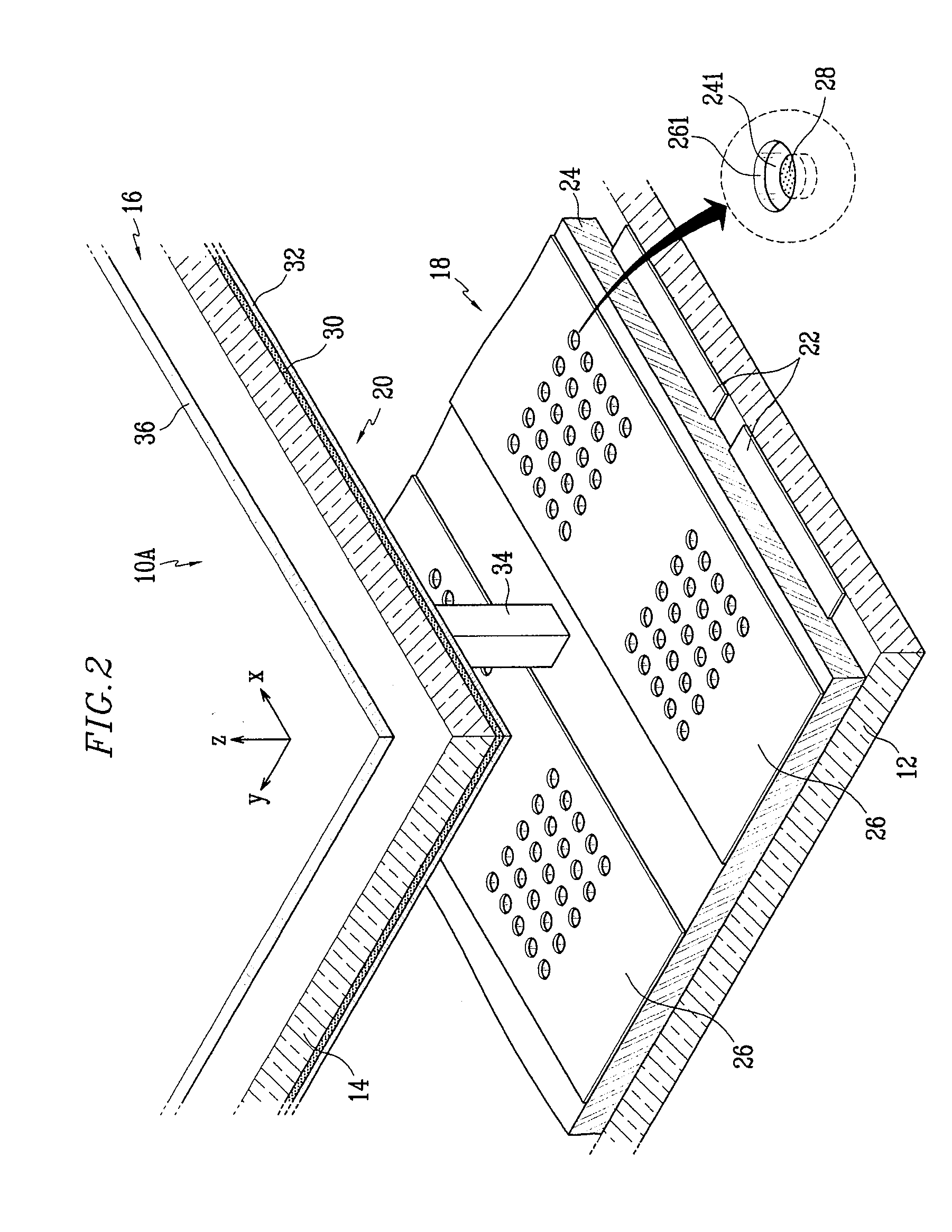
[0040]FIG. 1 is a partial exploded perspective view of a light emission device according to an exemplary embodiment of the present invention, FIG. 2 is a partial enlarged perspective view of the light emission device of FIG. 1, and FIG. 3 is a partial enlarged sectional view of the light emission device of FIG. 2.

[0041]Referrin...


PUM


Abstract

A diffusing member (or diffuser), a light emission device having the diffusing member, and a display using the light emission device are provided. The diffusing member is for uniformly diffusing light emitted from a surface light source of a backlight unit for a non-emissive device. The diffusing member has a light transmittance greater than or equal to 80%. The light emission device includes a vacuum vessel that has first and second substrates facing each other, an electron emission unit that is provided on the first substrate, a light emission unit that is provided on the second substrate and that emits light using electrons emitted from the electron emission unit, a spacer that uniformly maintains a gap between the first and second substrates, and a diffusing member that is located above the second substrate.

Description

CROSS-REFERENCE TO RELATED APPLICATION[0001]This application claims priority to and the benefit of Korean Patent Application No. 10-2006-0115142, filed on Nov. 21, 2006, in the Korean Intellectual Property Office, the entire content of which is incorporated herein by reference.BACKGROUND OF THE INVENTION[0002]1. Field of the Invention[0003]The present invention relates to a light emission device and a display having the light emission device, and more particularly, to a diffusing member (or diffuser) of the light emission device.[0004]2. Description of Related Art[0005]A liquid crystal display is a non-emissive display that displays an image using an external light source. The liquid crystal panel includes a liquid crystal panel assembly and a backlight unit for emitting light toward the liquid crystal panel assembly. The liquid crystal panel assembly receives the light from the backlight unit and selectively transmits or blocks the light using a liquid crystal layer, thereby displa...

Claims


Application Information

Patent Timeline
IPC IPC(8): H01J63/04G02B5/02G02F1/13357
CPCG02F1/133606H01J63/04H01J61/305G02F1/1335B82Y40/00
Inventor KANG, SU-JOUNG
Owner SAMSUNG SDI CO LTD
Why Eureka
Eureka Blog
Learn More