
Accurate signal detection in a wireless environment

a wireless environment and signal detection technology, applied in the field can solve the problems of unnecessarily consuming power, consuming more power, and consuming power, and achieve the effects of accurate signal detection, saving power, and improving the data throughput of wireless communication devices

Inactive Publication Date: 2008-05-22
AVAGO TECH INT SALES PTE LTD
View PDF2 Cites 30 Cited by
  • Summary
  • Abstract
  • Description
  • Claims
  • Application Information

AI Technical Summary

Benefits of technology

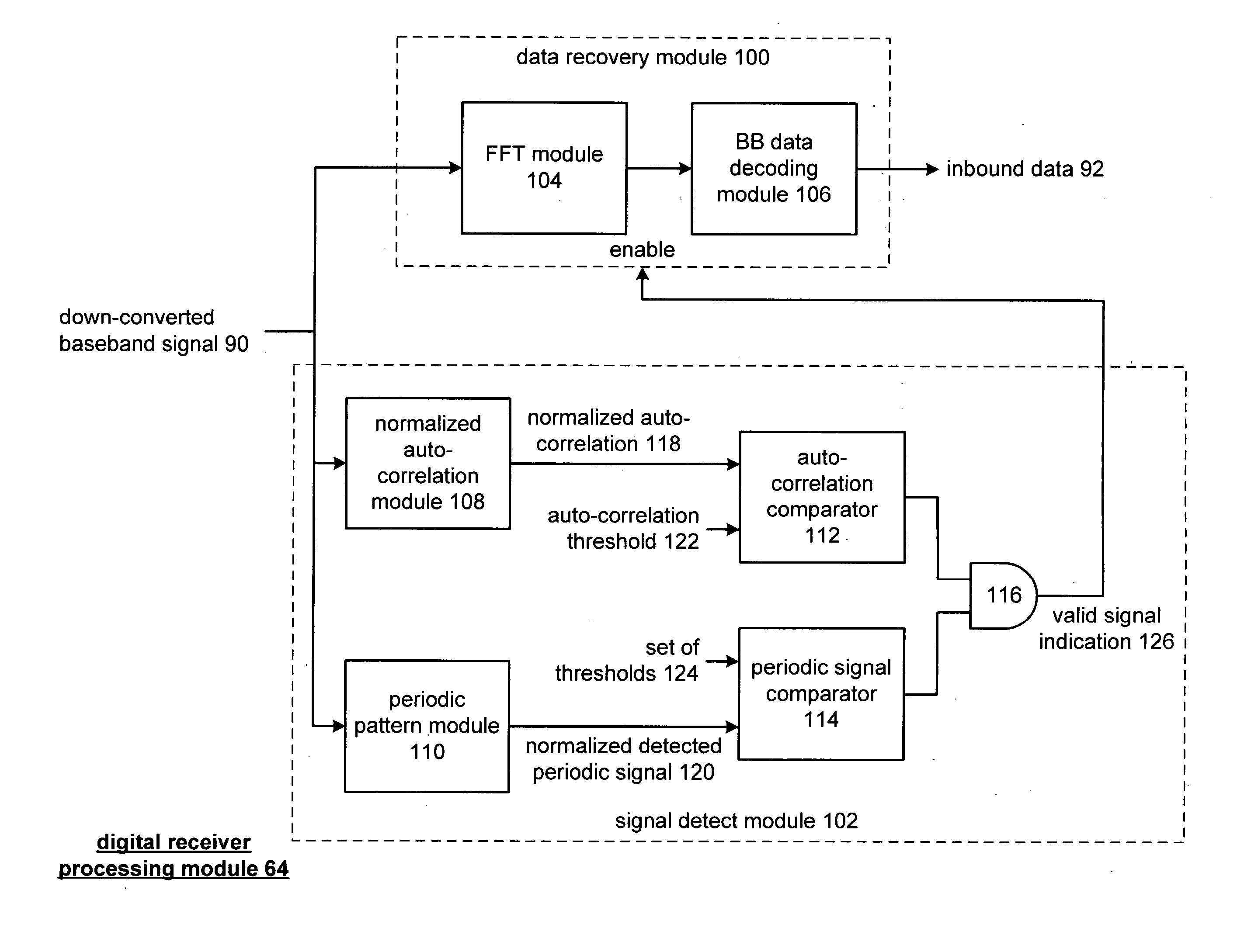
The present invention provides a method and apparatus for accurate signal detection in a wireless communication environment. This method involves receiving a radio frequency signal, converting it to baseband signals, and performing a normalized auto correlation and periodic pattern detection on the baseband signals. The results are then compared with thresholds to determine if the signal is valid. This method helps to eliminate false-positive detection of invalid signals, conserving power and improving data throughput of wireless communication devices.

Problems solved by technology

Typically, when the wireless communication devices are in the monitoring mode (i.e., seeking the preamble), they are in a limited operational state to reduce power consumption.
When the prescribed preamble is detected, the wireless communication device becomes fully operational and thus is consuming more power.
When this occurs, the wireless communication device is fully activated and thus consumes power unnecessarily.
In addition, such false positive detections limits data throughput of the wireless communication device since it is processing invalid data.

Method used


Image

  • Accurate signal detection in a wireless environment
  • Accurate signal detection in a wireless environment
  • Accurate signal detection in a wireless environment

Examples


Embodiment Construction

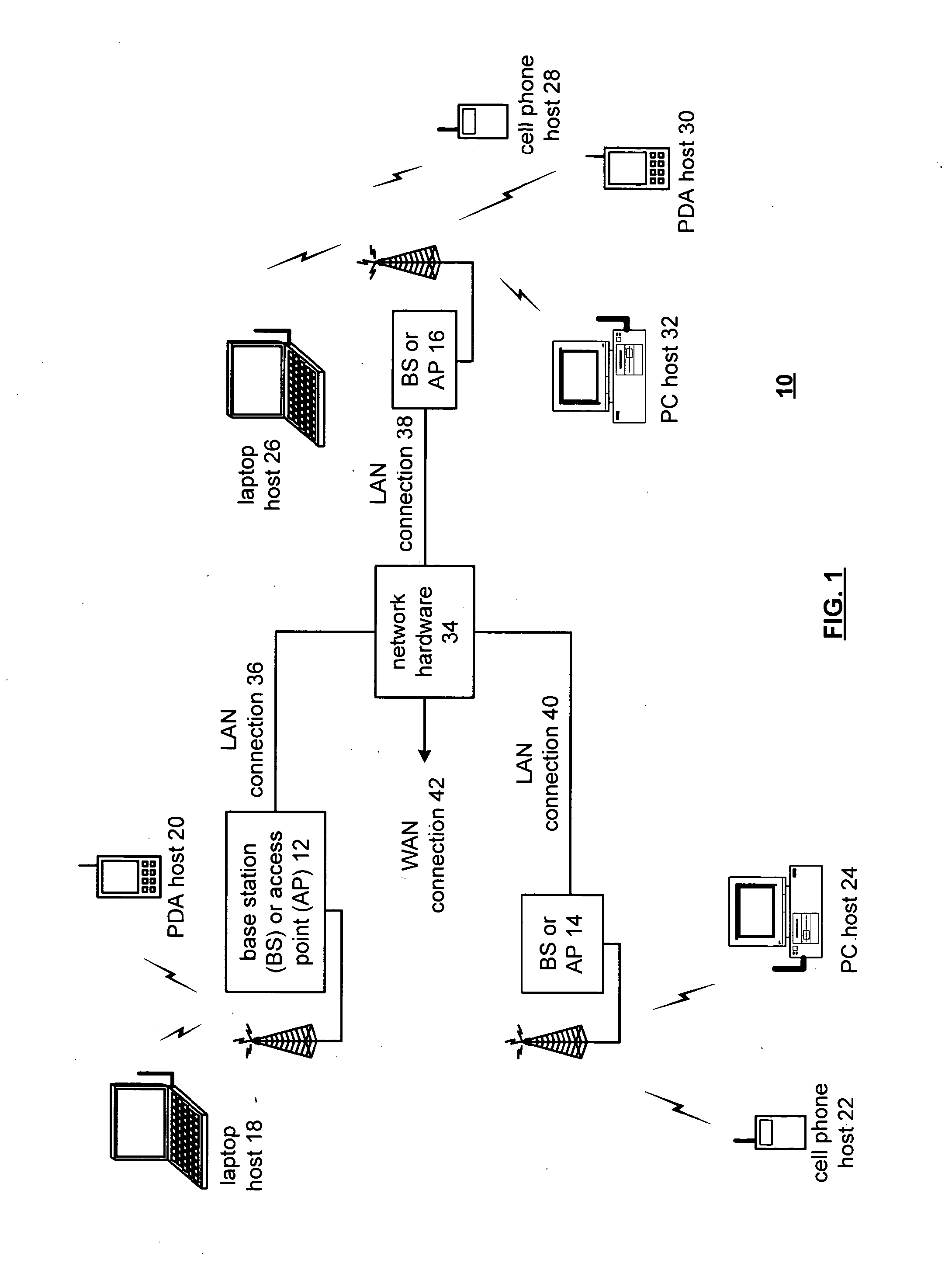
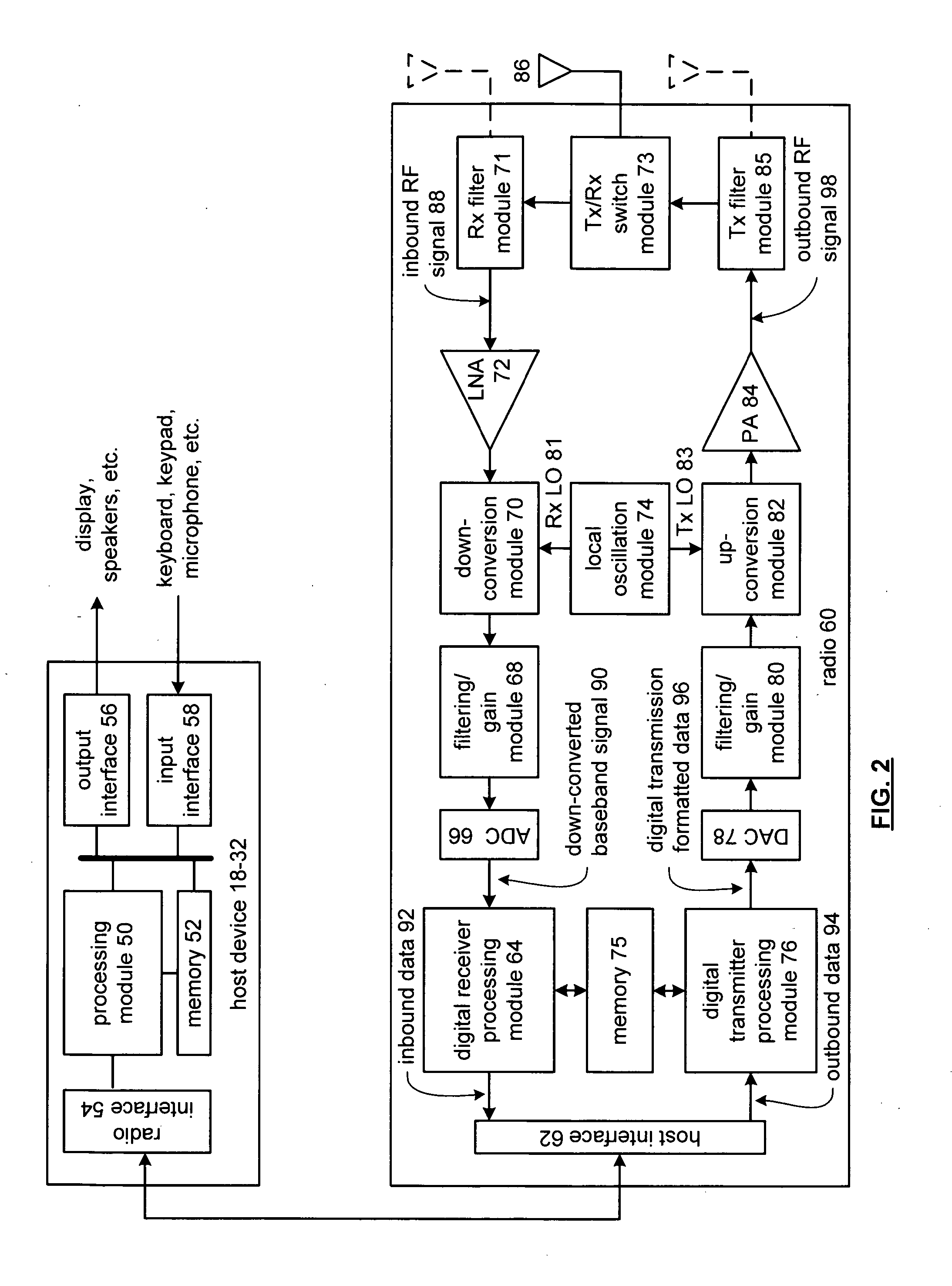
[0024]FIG. 1 is a schematic block diagram illustrating a communication system 10 that includes a plurality of base stations and / or access points 12-16, a plurality of wireless communication devices 18-32 and a network hardware component 34. The wireless communication devices 18-32 may be laptop host computers 18 and 26, personal digital assistant hosts 20 and 30, personal computer hosts 24 and 32 and / or cellular telephone hosts 22 and 28. The details of the wireless communication devices will be described in greater detail with reference to FIG. 2.

[0025] The base stations or access points 12-16 are operably coupled to the network hardware 34 via local area network connections 36, 38 and 40. The network hardware 34, which may be a router, switch, bridge, modem, system controller, et cetera provides a wide area network connection 42 for the communication system 10. Each of the base stations or access points 12-16 has an associated antenna or antenna array to communicate with the wire...


PUM


Abstract

A method for accurate signal detection begins by receiving a radio frequency signal, which is then converted into baseband signals. The processing then continues by performing a normalized auto correlation on the down-converted baseband signal to produce a normalized auto correlation signal. The process continues by performing a periodic pattern detection on the down-converted baseband signal to produce a normalized detected periodic signal. The process then continues by comparing the normalized auto correlation value with an auto correlation threshold and by comparing the normalized detected periodic signal with a set of thresholds. When the normalized auto correlation value compares favorably with the auto correlation threshold and when the normalized detected periodic signal compares favorably with the set of thresholds, the down-converted baseband signal is indicated to be a valid signal.

Description

CROSS REFERENCE TO RELATED APPLICATIONS [0001] The present U.S. Utility Patent Application claims priority pursuant to 35 U.S.C. § 120, as a continuation, to the following U.S. Utility Patent Application which is hereby incorporated herein by reference in its entirety and made part of the present U.S. Utility Patent Application for all purposes: [0002] U.S. Utility Application Serial No. 10 / 817,542, entitled “Accurate Signal [0003] Detection in a Wireless Environment,” (Attorney Docket No. BP3185), filed [0004] Apr. 2, 2004, pending, which claims priority as a continuation-in-part application [0005] to U.S. Utility Application Ser. No. 10 / 757,931, now U.S. Pat. No. 7,181,187, [0006] entitled “RF Transmitter Having Improved Out of Band Attenuation” (Attorney [0007] Docket No. BP3184), filed Jan. 15, 2004.BACKGROUND OF THE INVENTION [0008] 1. Technical Field of the Invention [0009] This invention relates generally to wireless communication systems and more particularly to accurate sig...

Claims


Application Information

Patent Timeline
Patent Type & Authority Applications(United States)
IPC IPC(8): H03D1/00H04L7/04H04L7/08H04L27/06H04L27/26
CPCH04L7/041H04L27/2647H04L7/08
Inventor TRACHEWSKY, JASON A.CORRY, ALAN
Owner AVAGO TECH INT SALES PTE LTD
Learn More