
Fuel cell system apparatus

a fuel cell and system apparatus technology, applied in the field of fuel cell systems, can solve the problems of undesirable operation of fuel cell stacks at their ocv, limiting the number of bop devices and/or limiting the time that the bop devices may be sourced, and the plant (bop) devices supporting the operation of fuel cell stacks are not designed for operation at the reduced voltage provided, so as to improve the voltage control of the fuel cell stack and increase the power efficiency of the fuel cell system

Inactive Publication Date: 2008-05-22
BDF IP HLDG
View PDF26 Cites 22 Cited by
  • Summary
  • Abstract
  • Description
  • Claims
  • Application Information

AI Technical Summary

Benefits of technology

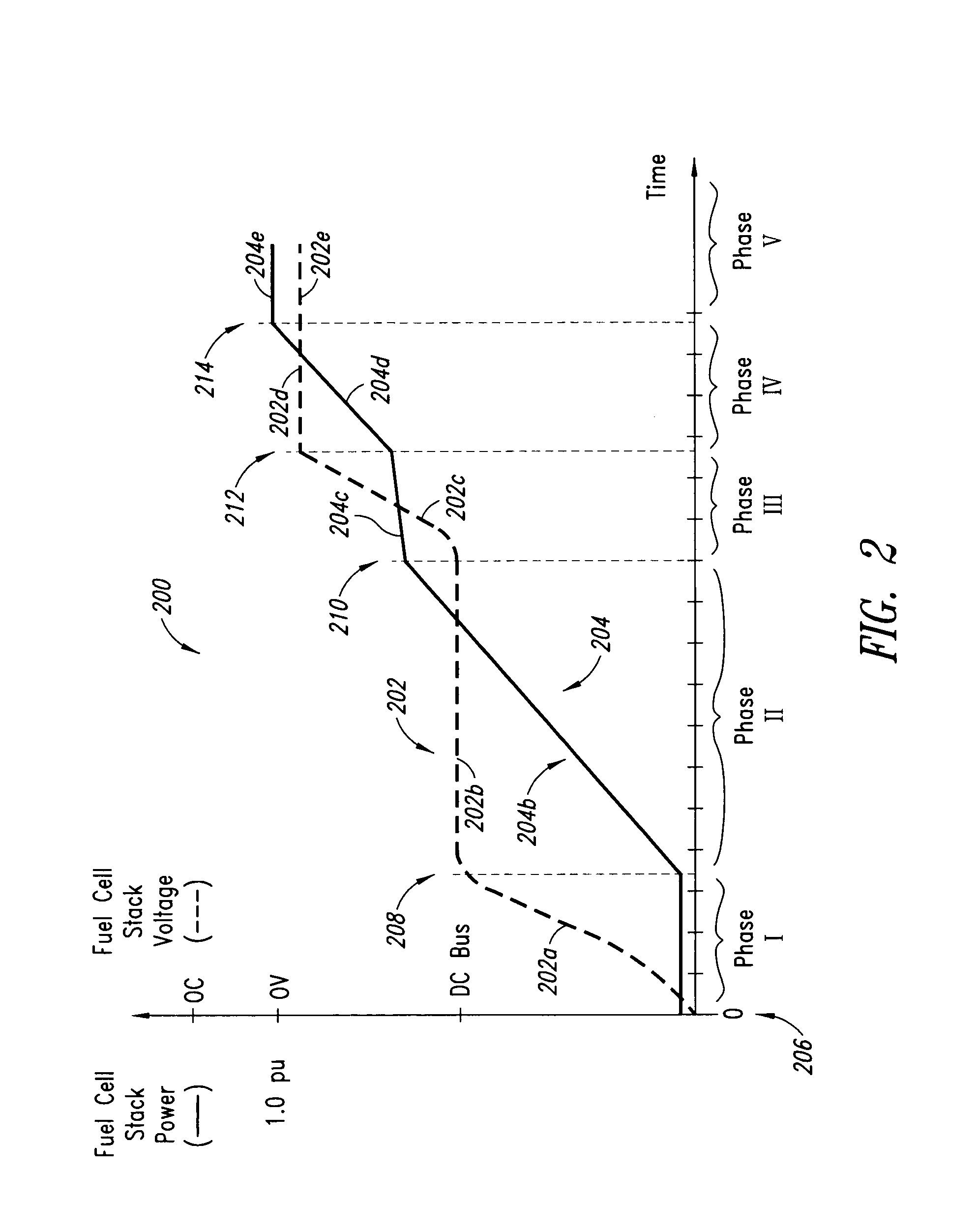
[0015]Although there have been advances in the field, there remains a need in the art for improving voltage control of the fuel cell stack during the start-up

Problems solved by technology

Some balance of plant (BOP) devices supporting operation of a fuel cell stack are not designed for operation at the reduced voltages provided by the fuel cells during start-up.
However, such auxiliary power supplies may be limited in their output current and / or energy capacity, thereby limiting the number of BOP devices and / or limiting the time that the BOP devices may be sourced.
Operating a fuel cell stack at its OCV is undesirable because of potential thinning of the fuel cell stack membranes and / or cathode corrosion.
However, timing operation of the contactors to coordinate operation of the fuel cell stack, the BOP loads, and the auxiliary power supplies is difficult.
Improper coordination of the operation of the contactors may result in the above-described damage to the fuel cell stack.
Furthermore, improper coordination of the operation of the contactors may cause other problems, such as back-driving the fuel cell stack.
When the fuel cell stack is providing the power used by its BOP devices, power losses occur in the DC / DC converter (and the attendant transmission wires) because the power must first pass through the DC / DC converter.

Method used


Image

  • Fuel cell system apparatus
  • Fuel cell system apparatus
  • Fuel cell system apparatus

Examples


first embodiment

[0093]FIGS. 4A-4C are schematic diagrams of alternative embodiments of the power source 104 (FIG. 1). FIG. 4A illustrates the power source 104 comprising a battery, a plurality of batteries, or a plurality of battery cells (generally denoted with reference numeral 402). Any type of suitable battery may be used, for example, a rechargeable battery.

second embodiment

[0094]FIG. 4B illustrates the power source 104 comprising a super capacitor, an ultracapacitor, a plurality of super capacitors or ultracapacitors, or super capacitor or ultracapacitor cells (generally denoted with reference numeral 404). The super capacitors 404 may be coupled to other devices, such as the exemplary diodes 408. Any type of suitable capacitor 406 may be used.

third embodiment

[0095]FIG. 4C illustrates the power source 104 comprising an alternating current (AC) system 410. The AC system 410 comprises an AC power source 412 and an alternating current to direct current (AC / DC) converter 416. The AC power source 412 may be any suitable AC machine that is operable in a power generation mode. For example, the AC power source 412 may be mechanically coupled to a fossil fuel burning engine or the like. As another example, the AC power source 412 may be coupled to a wheel or axle of a vehicle and used to propel the vehicle when operated as a motor, and used as a brake to slow or stop the vehicle. When operated as a brake, the AC power source 412 may operate as a generator that converts the kinetic energy of the slowing or stopping vehicle into electrical power. Any type of suitable AC power source 412 may be used.

[0096]The AC / DC converter 414 converts AC power received from the AC power source 412 into DC power. The DC power is then transferred onto the first DC ...


PUM


Abstract

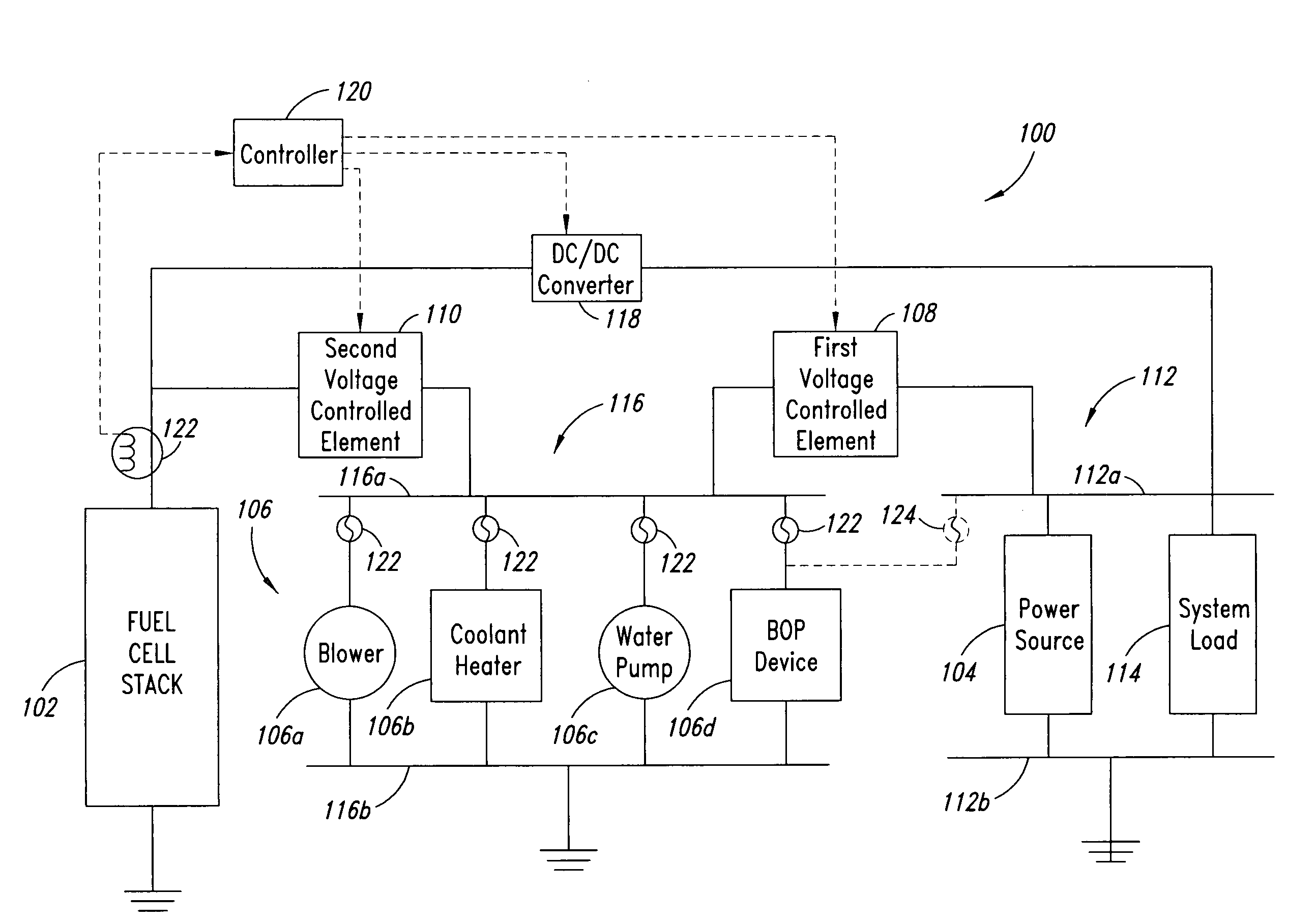
A power system is disclosed that includes a fuel cell stack primary power source, a secondary power source, a first direct current bus, a first voltage controlled element that electrically couples power from the secondary power source to the first direct current bus when a voltage across the secondary power source is greater than a voltage across the fuel cell stack primary power source, a second voltage controlled element that electrically couples power from the fuel cell stack primary power source to the first direct current bus when the voltage across the fuel cell stack primary power source is greater than the voltage across the secondary power source, and at least one balance of plant load electrically coupled to the first direct current bus.

Description

BACKGROUND OF THE INVENTION[0001]1. Field of the Invention[0002]This disclosure generally relates to fuel cell systems suitable for producing electrical power.[0003]2. Description of the Related Art[0004]Electrochemical fuel cells convert fuel and oxidant to electricity. Solid polymer electrochemical fuel cells generally employ a membrane electrode assembly (“MEA”) which includes an ion exchange membrane or solid polymer electrolyte disposed between two electrodes typically comprising a layer of porous, electrically conductive sheet material, such as carbon fiber paper or carbon cloth. The MEA contains a layer of catalyst, typically in the form of finely comminuted platinum, at each membrane electrode interface to induce the desired electrochemical reaction. In operation, the electrodes are electrically coupled for conducting electrons between the electrodes through an external circuit. Typically, a number of fuel cells are electrically coupled in series to form a fuel cell stack su...

Claims


Application Information

Patent Timeline
IPC IPC(8): H01M8/04
CPCH01M8/04559H01M8/04567H01M8/0494Y02T90/32H01M16/006H01M2250/20Y02E60/50H01M8/04947Y02E60/10Y02T90/40
Inventor GALLAGHER, EMERSON R.
Owner BDF IP HLDG
Learn More