
Battery pack and fabricating method thereof

Active Publication Date: 2008-05-22
SAMSUNG SDI CO LTD
View PDF9 Cites 42 Cited by
  • Summary
  • Abstract
  • Description
  • Claims
  • Application Information

AI Technical Summary

Benefits of technology

[0012]It is therefore an object of the present invention to provide improved battery pack and improved process for manufacturing packs.
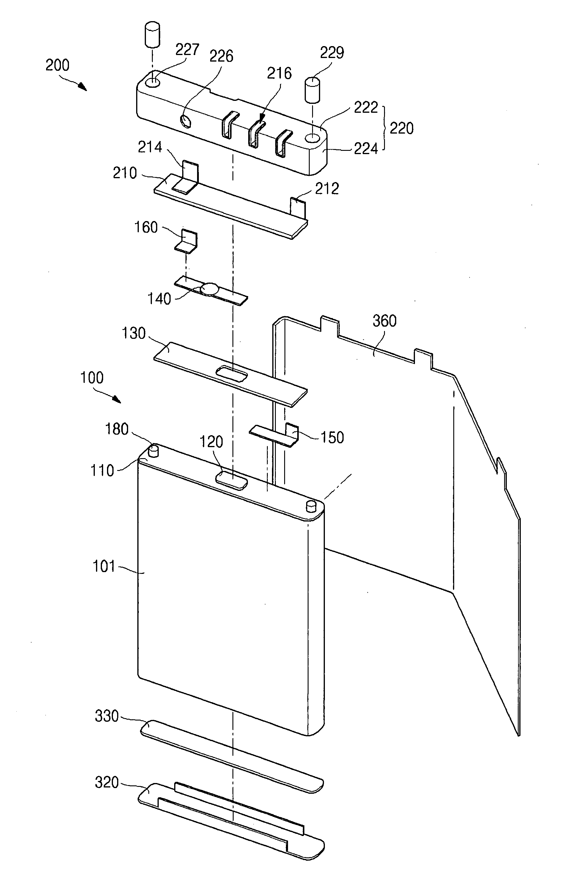
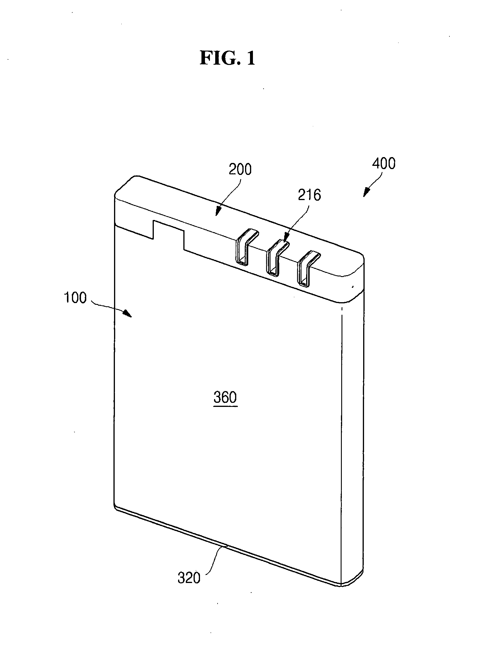
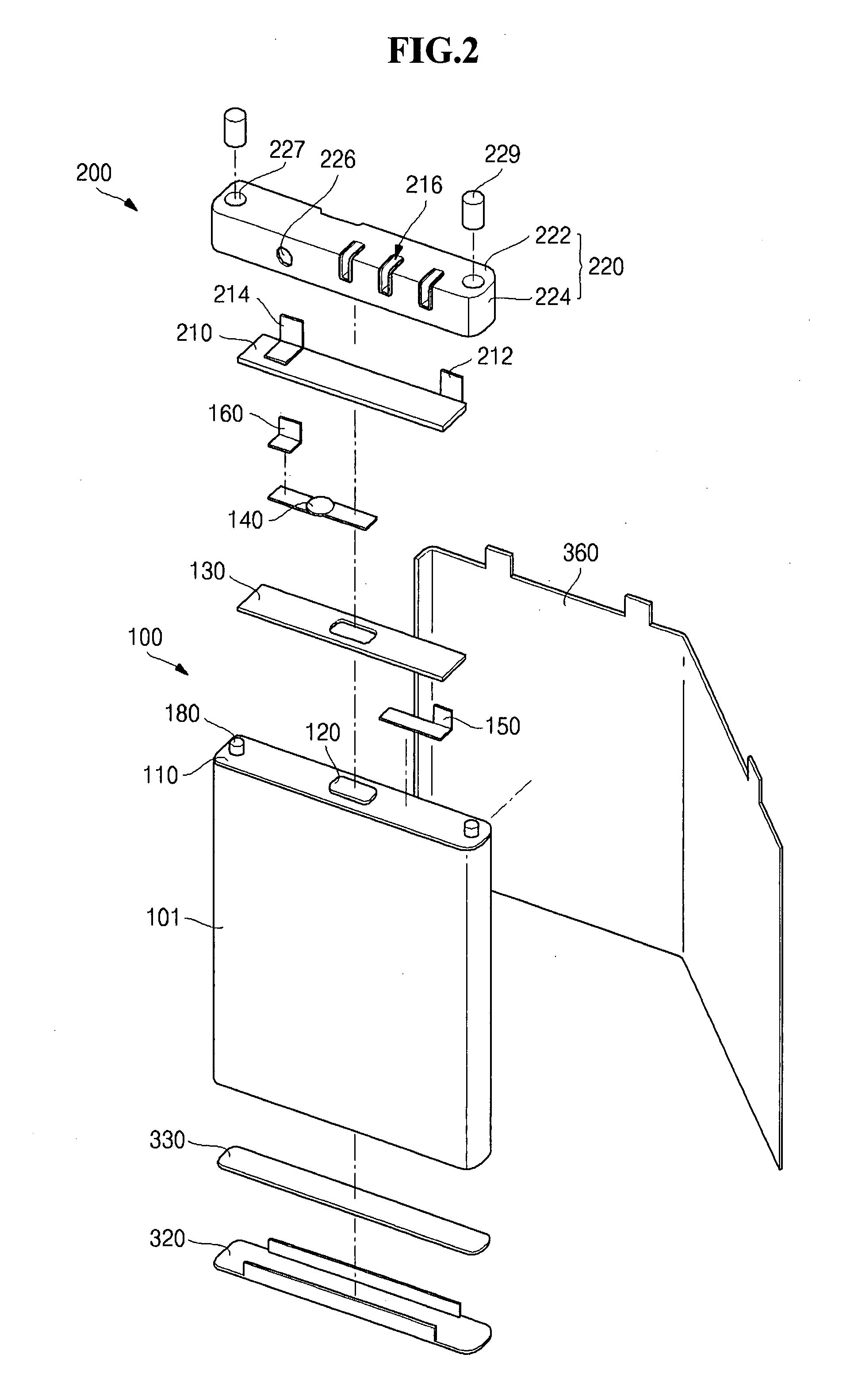
[0013]It is another object to provide a battery pack and a fabricating method thereof capable of increasing the coupling strength between a bare cell and a circuit accessory thus preventing the circuit accessory from being separated from the bare cell due to external forces like bending, twisting and falling of a battery, by forming a fixing member protruding from the upper part of the bare cell, and coupling the fixing member with a fixing member hole of the circuit accessory that is formed in advance by injection molding in the type of the fixing member being laid across the fixing member hole.

Problems solved by technology

Accordingly, the instability of the electrical connection between the battery pack and the external electronic device becomes a problem.
When the pad-type external terminal of the conventional battery pack is coupled with the connection part of the external electronic device with pushing contacts, when the number of the pushing increases, a coating layer on the surface of the external terminal might peel off or crack.
When such cracking of the coating layer of an external terminal of the battery pack gets serious, the electrical flow between the battery pack and the external electronic device might become out of order.
Also, because the pad-type external terminal of the battery pack is disposed in the form of being exposed directly to the outside of the batter pack, it might be corroded by moisture in the air as a long period of time elapses.
However, because the connector type external terminal has a complicated shape and a plurality of openings, it is difficult to apply the resin molding method of filling resin between the protection circuit module and the bare cell during the manufacture when the battery pack having a connector type external terminal.

Method used


Image

  • Battery pack and fabricating method thereof
  • Battery pack and fabricating method thereof
  • Battery pack and fabricating method thereof

Examples


Embodiment Construction

[0065]Hereinafter, preferred embodiments of the present invention will be described in detail with reference to the accompanying drawings. The aspects and features of the present invention and methods for achieving the aspects and features will be apparent by referring to the embodiments to be described in detail with reference to the accompanying drawings. However, the present invention is not limited to the embodiments disclosed hereinafter, but can be implemented in diverse forms. The matters defined in the description, such as the detailed construction and elements, are nothing but specific details provided to assist those of ordinary skill in the art in a comprehensive understanding of the invention, and the present invention is only defined within the scope of the appended claims. In the entire description of the present invention, the same drawing reference numerals are used for the same elements across various figures.

[0066]Turning now to the drawings, FIGS. 1 through 4 coll...


PUM

PropertyMeasurementUnit
Thicknessaaaaaaaaaa
Diameteraaaaaaaaaa
Sizeaaaaaaaaaa

Abstract

Disclosed are a battery pack and a fabricating method which can increase the coupling strength of a bare cell and a circuit accessory and prevent the circuit accessory from being separated from the bare cell due to external forces such as bending, twisting and falling of a battery, by forming a fixing member protruding from the upper part of the bare cell, and coupling the fixing member with a fixing member hole of the circuit accessory formed in advance by injection molding in the type of the fixing member being laid across the fixing member hole. The battery pack includes: a bare cell having a cap plate on the upper part of the bare cell; and a circuit accessory coupled with the upper part of the bare cell, wherein a fixing member is formed to protrude from the outer surface of the cap plate, a fixing member hole corresponding to the fixing member is formed on the circuit accessory, and the fixing member is inserted in and is coupled with the fixing member hole.

Description

CLAIM OF PRIORITY[0001]This application makes reference to, incorporates the same herein, and claims all benefits accruing under 35 U.S.C. §119 from an application earlier filled in the Korean Intellectual Property Office on 20 Nov. 2006 and there duly assigned Serial No. 10-2006-0114423.BACKGROUND OF THE INVENTION[0002]1. Field of the Invention[0003]The present invention relates to a battery pack. More specifically, the present invention relates to a battery pack and a fabricating method thereof which can increase a coupling strength between a bare cell and a circuit accessory thus prevent the circuit accessory from being separated from the bare cell due to external forces like bending, twisting and falling of a battery, by forming a fixing member protruding from the upper part of the bare cell, and coupling the fixing member with a fixing member hole of the circuit accessory formed in advance by injection molding in the type of the fixing member being laid across the fixing member...

Claims


Application Information

Patent Timeline
IPC IPC(8): H01M10/36H01M10/38H01M50/528
CPCH01M2/0404H01M2/0439H01M2/06H01M2/22H01M2/34Y10T29/49108H01M10/0436H01M10/058H01M10/425H01M2200/00H01M2/345Y02E60/10H01M50/528H01M50/578Y02P70/50H01M50/284H01M50/202H01M50/247H01M50/296
Inventor YOON, HEUISANG
Owner SAMSUNG SDI CO LTD
Learn More