
Control system and vehicle

a control system and vehicle technology, applied in the direction of electric control, machines/engines, instruments, etc., can solve the problems of difficult adjustment of the difficulty of disconnecting the gears, and the difficulty of a less skilled driver to adjust the output of the engine, described above,

Active Publication Date: 2008-05-22
YAMAHA MOTOR CO LTD
View PDF16 Cites 14 Cited by
  • Summary
  • Abstract
  • Description
  • Claims
  • Application Information

AI Technical Summary

Benefits of technology

[0012]In order to overcome the problems described above, preferred embodiments of the present invention provide a control system that enables comfortable driving of a vehicle with outstanding drivability, and the vehicle including the same.

Problems solved by technology

In such situations, since the gearshift is operated while the power is being transmitted from the crankshaft to the main shaft, it is difficult to disconnect the gears.
The adjustment of the output of the engine, described above, is difficult for a less skilled driver.
Therefore, if the less skilled driver performs the clutchless shifting, in some cases, the gearshift cannot be performed smoothly.
However, if the output torque of the engine is adjusted based on the transmission directions of the torque, unnecessary adjustments of the torque are performed in some cases.
This produces uncomfortable feelings to the driver.

Method used


Image

  • Control system and vehicle
  • Control system and vehicle
  • Control system and vehicle

Examples


Embodiment Construction

[0060]A control system and a vehicle including the same according to preferred embodiments of the present invention will now be described with reference to the drawings. Note that a motorcycle as an example of the vehicle will be described below.

(1) General Structure of a Motorcycle

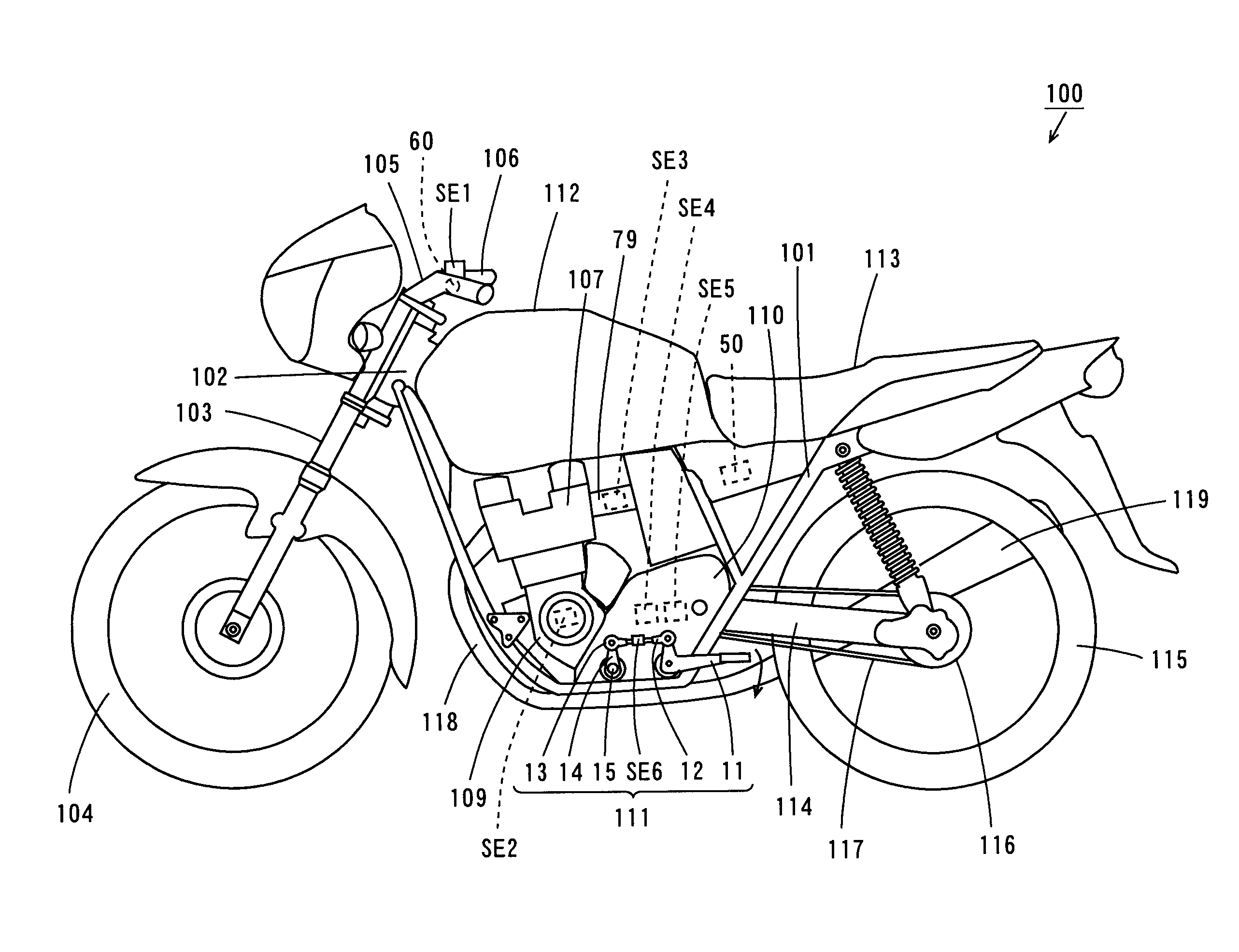
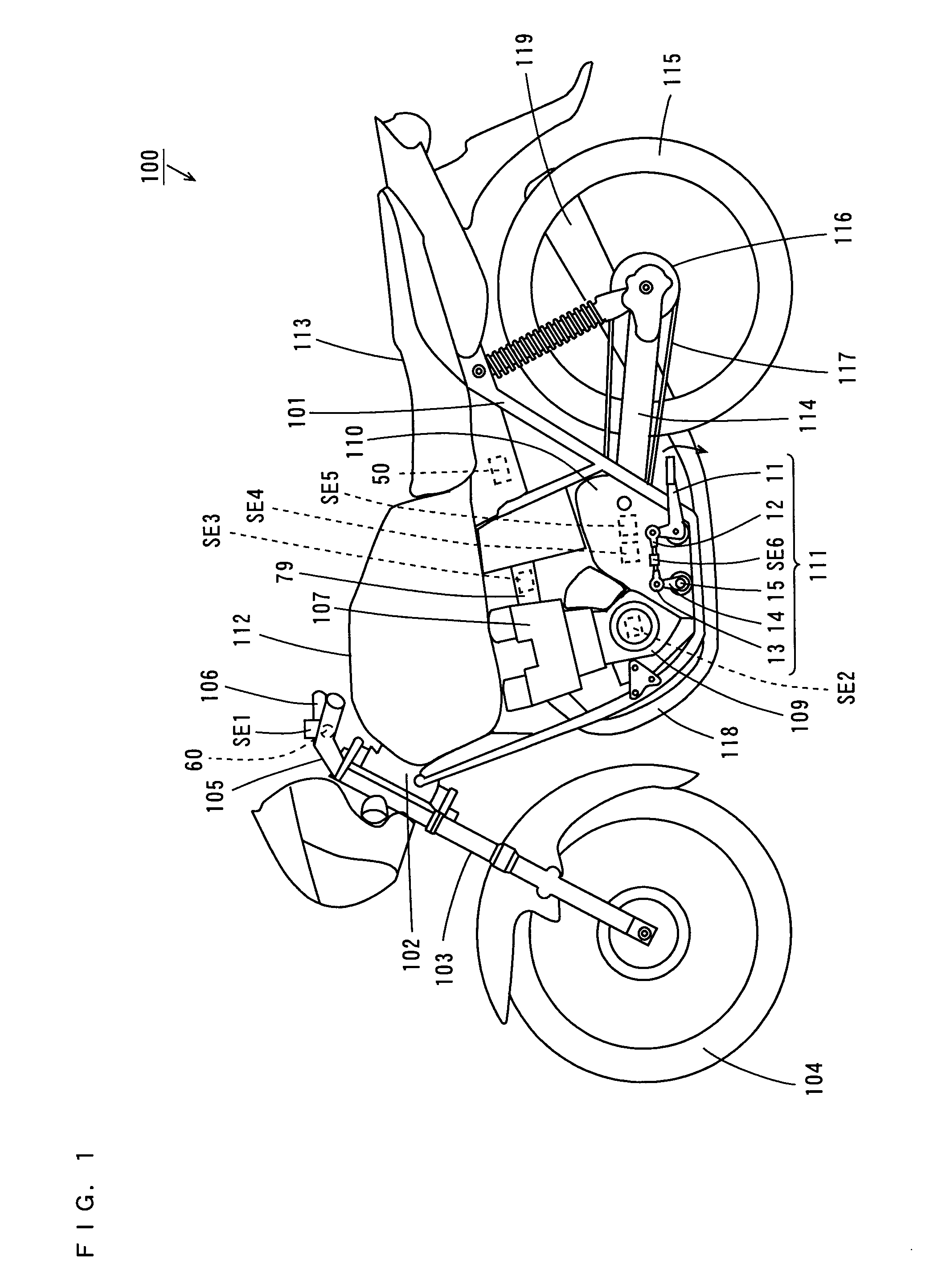
[0061]FIG. 1 is a schematic side view of a motorcycle according to the present preferred embodiment.

[0062]In the motorcycle 100 of FIG. 1, a head pipe 102 is provided at the front end of a main body frame 101. A front fork 103 is provided at the head pipe 102 so as to be able to swing from side to side. At the lower end of the front fork 103, a front wheel 104 is rotatably supported. A handle 105 is provided at the upper end of the head pipe 102.

[0063]The handle 105 is provided with an accelerator grip 106, an accelerator opening sensor SE1 and a notification lamp 60. The accelerator opening sensor SE1 detects an operation amount of the accelerator grip 106 by a driver (hereinafter referred to as “an acce...


PUM


Abstract

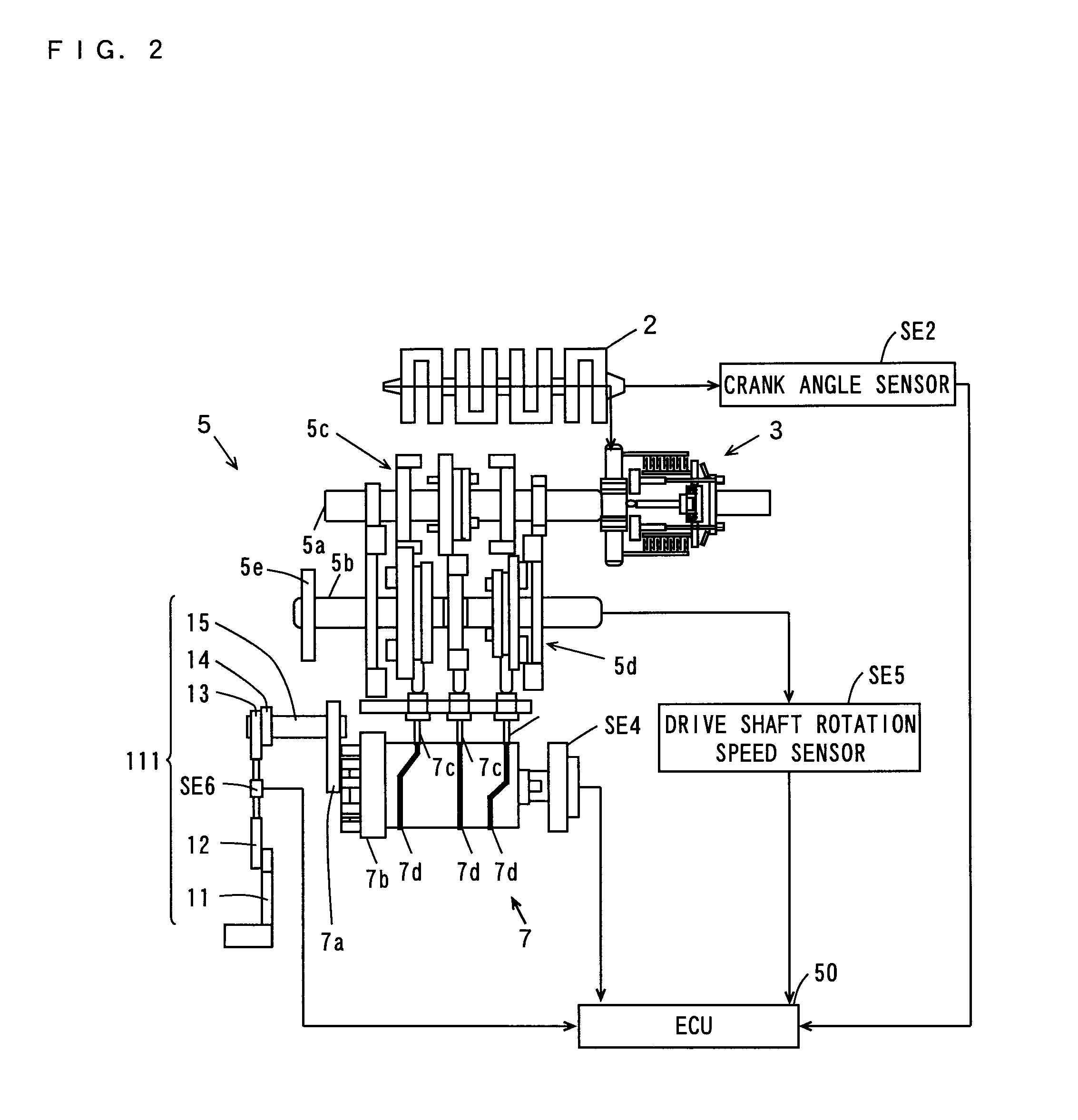
A motorcycle includes a transmission, an ECU, an engine and a transmission operating mechanism. The engine has a crank. The transmission operating mechanism includes a shift pedal and a load sensor. The load sensor detects an operation of the shift pedal by a driver, and applies a detected value to the ECU. The ECU decreases an output of the engine when a torque (driving force) having at least a predetermined value is transmitted from the crank to the transmission when a shift operation of the driver is detected by the load sensor. Moreover, the ECU does not decrease the output when the torque transmitted from the crank to the transmission is less than the predetermined value when the shift operation of the driver is detected by the load sensor.

Description

BACKGROUND OF THE INVENTION[0001]1. Field of the Invention[0002]The present invention relates to a control system that assists a shifting operation of a transmission and a vehicle including the same.[0003]2. Description of the Related Art[0004]When operating a gearshift in a vehicle with a manual transmission, first, a driver usually disconnects a clutch. Thus, power transmission from a crankshaft of an engine to a main shaft of the transmission is stopped, so that gears are easily disconnected. In this state, the driver performs a shifting operation and changes gear positions. Finally, the driver connects the clutch, so that the power is transmitted from the crankshaft to the main shaft. In this way, the gearshift is completed.[0005]During a race or other high speed activities, the gearshift is required to be operated quickly. Therefore, in some situations, the driver operates the gearshift without a clutch operation (hereinafter referred to as “clutchless shifting”). In such situa...

Claims


Application Information

Patent Timeline
IPC IPC(8): F16H59/14G06F19/00B60K8/00F02D29/00F02D41/04F02D45/00F16H59/24F16H59/42F16H59/44F16H61/04F16H61/68F16H61/682F16H63/50
CPCB60W10/06B60W10/11B60W30/18172B60W30/19Y10T477/677B60W2510/0657B60W2710/0666B60Y2200/12F16H63/502B60W50/14
Inventor WATANABE, HIROTO
Owner YAMAHA MOTOR CO LTD
Learn More