Gas chromatography system architecture

a technology of gas chromatography and system architecture, which is applied in the field of gas chromatography systems, can solve the problems of increasing the design constraints of a system suitable for down-hole operation, increasing the design constraints of a system, and requiring a relatively large supply of carrier gas, so as to facilitate thermal management and improve the operability and reliability of gas chromatographic analysis.

a technology of gas chromatography and system architecture, which is applied in the field of gas chromatography systems, can solve the problems of increasing the design constraints of a system suitable for down-hole operation, increasing the design constraints of a system, and requiring a relatively large supply of carrier gas, so as to facilitate thermal management and improve the operability and reliability of gas chromatographic analysis.

US20080121016A1Inactive Publication Date: 2008-05-29SCHLUMBERGER TECH CORP

Image

  • Gas chromatography system architecture
  • Gas chromatography system architecture
  • Gas chromatography system architecture

Examples


Embodiment Construction

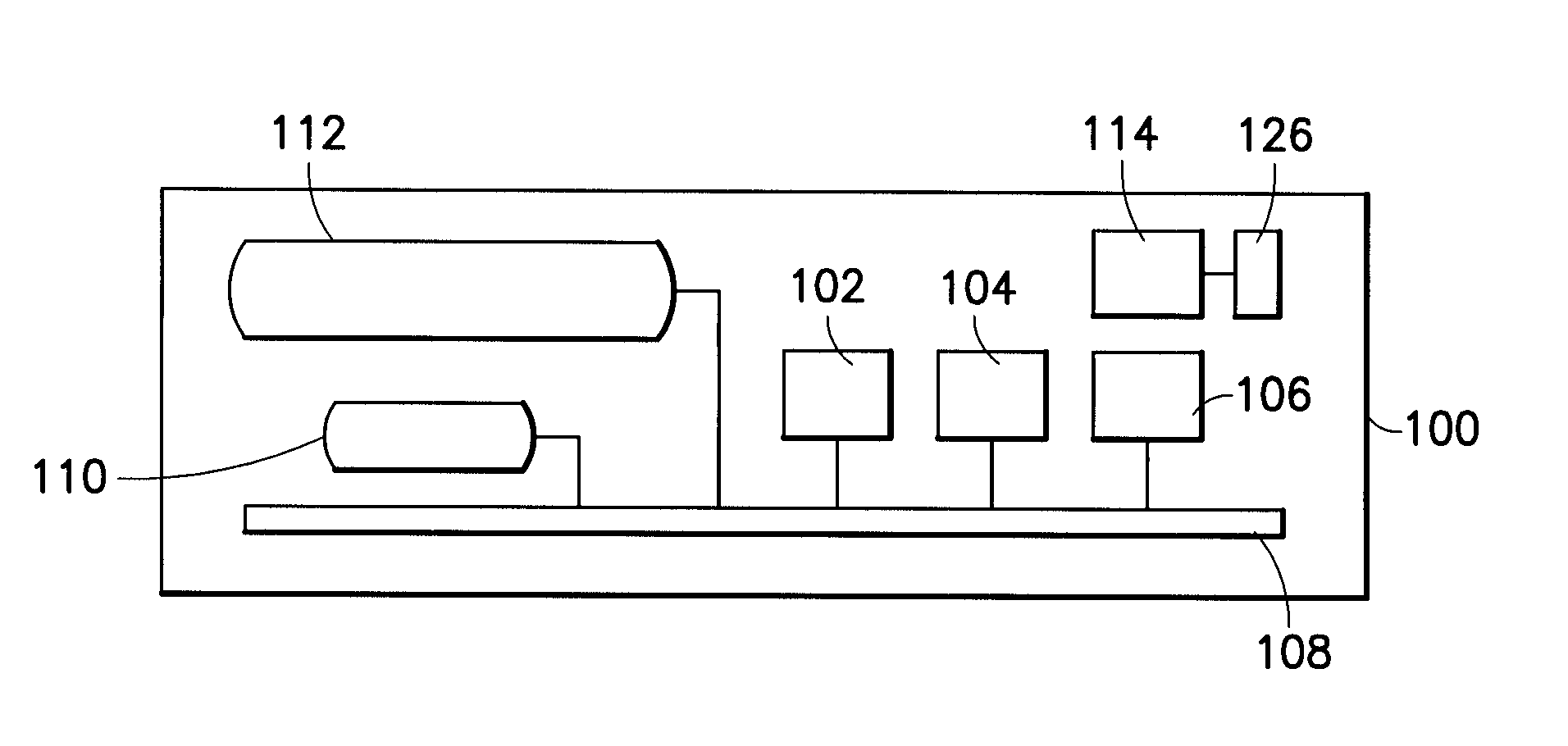
[0025]Embodiments of the invention and aspects thereof are directed to a gas chromatography apparatus and system that incorporates micro-scale components and may be suitable for use in a variety of environments. Traditionally, gas chromatographic analysis is performed on the surface of the earth, usually in a laboratory or similar environment. A sample may be collected at a remote location or sample site, for example, an underground or underwater location, and then returned to a testing facility, such as a laboratory, for chromatographic analysis. As discussed above, although there have been some developments of portable gas chromatography systems, none have been suitable for down-hole applications. Therefore, to address these and other limitations in the prior art, aspects and embodiments of the invention are directed to a gas chromatography system having an architecture that allows for down-hole operation. For example, boreholes are typically small diameter holes having a diameter...


PUM


Abstract

A self-contained micro-scale gas chromatography system that includes a plurality of gas chromatography components arranged on a micro-fluidic platform with nearly zero dead volume “tubeless” fluidic connections for the gas chromatography components. The micro-fluidic platform includes a plurality of flow channels that provide fluid flow paths for a sample, carrier gas and waste gas through and among the micro-fluidic platform and the plurality of gas chromatography components. The system may also include an on-board supply of carrier gas and on-board waste management, as well as a thermal management scheme making the system suitable for use in oil and gas wells and also other remote environments.

Description

BACKGROUND[0001]1. Field of Invention[0002]The present invention relates to gas chromatography systems and, more particularly, to small-scale systems that may be suitable for operation in various environments.[0003]2. Discussion of Related Art[0004]Gas chromatography uses chromatographic columns to separate molecular species within a sample fluid and thereby to extract information about the sample fluid. A chromatographic column has a stationary phase fixed inside the column and a mobile phase which is a carrier gas, such as, helium that flows through the column. The sample is collected, injected into the column and then transported by the carrier gas into and through the column. If the sample is in a liquid state, the sample may first be injected into a vaporization chamber to be vaporized then transported through the column. As a sample progresses through the column, the individual molecular components are slowed down based on their affinity to the stationary phase. At the outlet ...

Claims


Application Information

Patent Timeline
29 May 2008
Publication
US20080121016A1
IPC
G01N30/04
CPC
B01L3/502715; B01L2200/18; G01N30/6095; G01N2030/8881; G01N2030/025; G01N2030/8854; G01N30/88
Inventors
SHAH, JAGDISH; BOSTROM, NEIL WILLIAM