Plasma type ignition plug

a technology of ignition plugs and plugs, which is applied in the direction of sparking plugs, instruments, machines/engines, etc., can solve the problems of difficulty in initiating spark discharg

Inactive Publication Date: 2008-05-29
DENSO CORP
View PDF1 Cites 14 Cited by
  • Summary
  • Abstract
  • Description
  • Claims
  • Application Information

AI Technical Summary

Benefits of technology

[0011]The present invention has been completed with the above view in mind and has an object to provide a plasma type ignition plug, having a negative electrode with a less wear when subjected to cathode sputtering, which has a less occurrence of an increase in a discharge voltage while realizing a stable ignition with a superior durability.
[0012]To achieve the above object, a first aspect of the present invention provides a plasma type ignition plug for igniting an internal combustion engine, comprising: a cylindrical ground electrode having a leading end whose bottom portion has a central area formed with an opening portion; a cylindrical insulating body, kept in abutting contact with an inside of the ground electrode and engaging the bottom portion of the ground electrode, which has an inner diametric portion defining a discharging airspace in communication with the opening portion of the ground electrode; and a center electrode fitted to the insulating body at a center thereof and having a leading end exposed to the discharging airspace at a position axially inward from a leading end face of the ground electrode. One of the ground electrode and the center electrode serves as a negative electrode and the other serves as a positive electrode. A voltage is applied across the ground electrode and the center electrode to initiate a spark discharge in the discharging airspace formed inside the insulating body to allow gas in the discharging airspace to eject from the opening portion of the ground electrode in a plasma state at a high temperature and high pressure for achieving an ignition in the internal combustion engine. A discharging distance fixing member, including an electrically conductive material replenishing section, made of an electrically conductive material available to melt when subjected to a heat of the gas in the plasma state, and an electrically conductive material replenished section to which the electrically conductive material is replenished, is covered on a surface of is the negative electrode for initiating the spark discharge between a surface of the discharging distance fixing member and the positive electrode so as to avoid a fluctuation in a spark discharge distance caused by a wear of the negative electrode due to a collision of gas in the plasma state.

Problems solved by technology

Accordingly, a long-term usage results in a difficulty of initiating the spark discharge with a fear of causing a misfiring of the internal combustion engine.

Method used


Image

  • Plasma type ignition plug
  • Plasma type ignition plug
  • Plasma type ignition plug

Examples


first embodiment

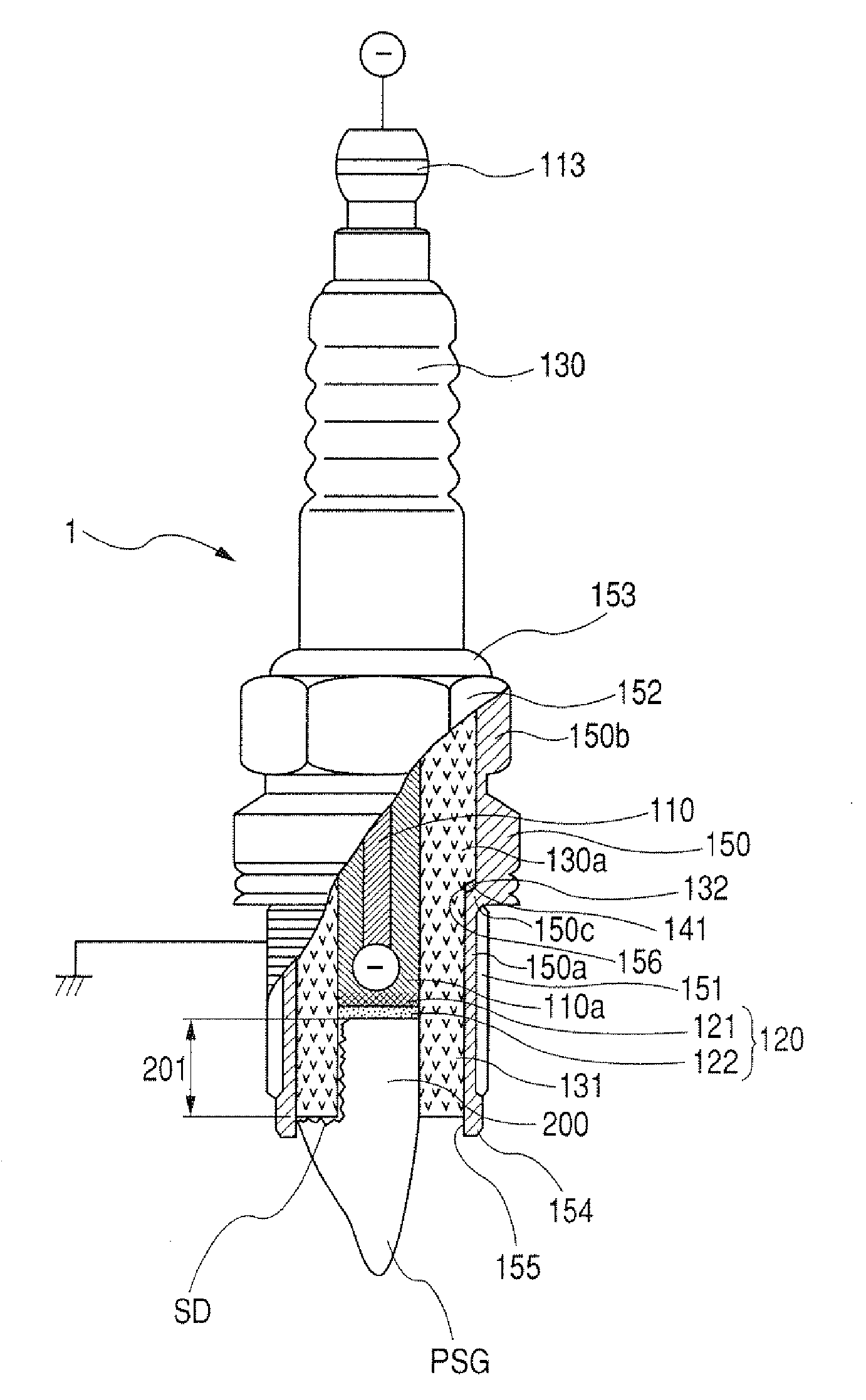
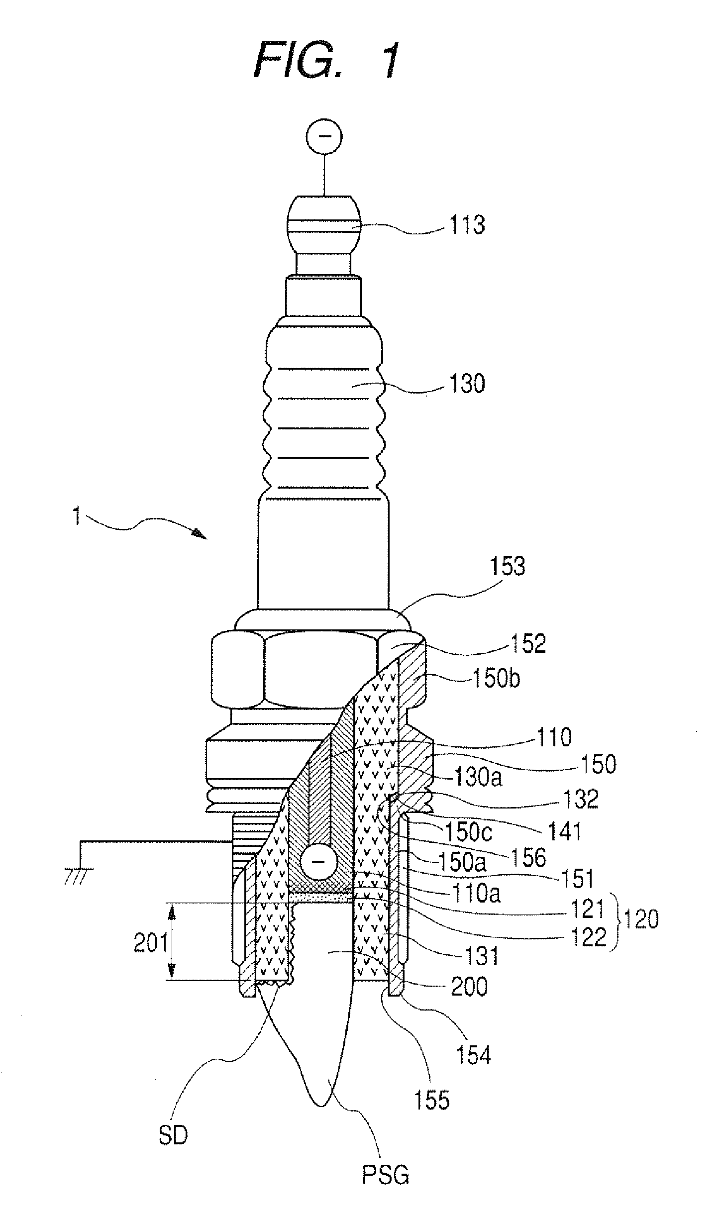
[0061]Now, a plasma type ignition plug of a first embodiment according to the present invention for use in an internal combustion engine will be described below in detail with reference to FIGS. 1 and 2.

[0062]FIG. 1 is a partially cross-sectional view showing an outline of the plasma type ignition plug of the first embodiment according to the present invention.

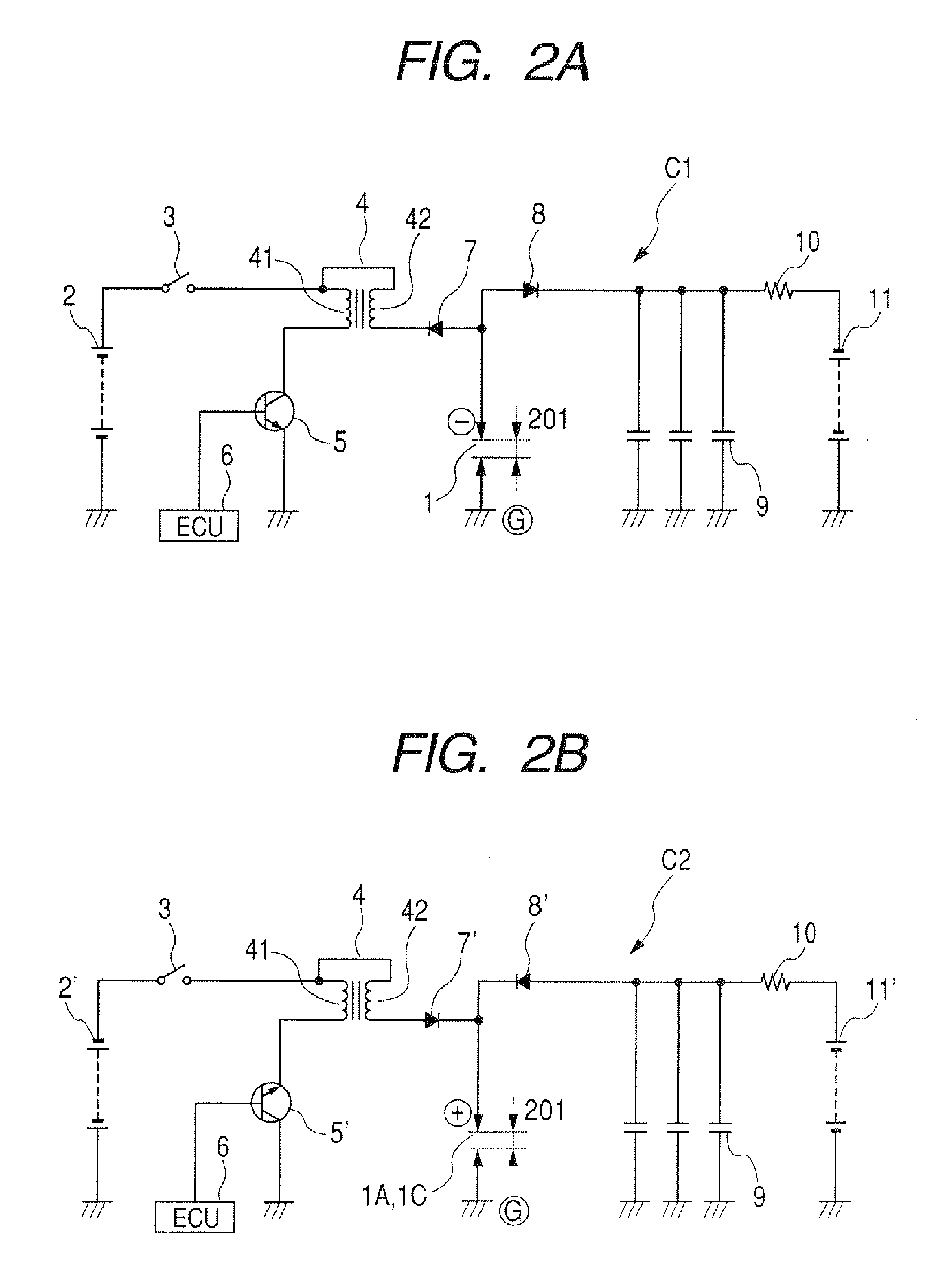
[0063]FIG. 2A is a circuit diagram showing one example of fundamental structures of the plasma type ignition plug of the first embodiment according to the present invention with a center electrode acting as a negative electrode. FIG. 2B is a circuit diagram showing the other example of the fundamental structures of the plasma type ignition plug of the first embodiment according to the present invention with the center electrode acting as a positive electrode.

[0064]As shown in FIG. 1, the plasma type spark plug 1 of the present embodiment comprises the center electrode 110 made of conductive metallic material and formed in a co...

second embodiment

[0112]A plasma type ignition plug 1A of a second embodiment according to the present invention will be described below in detail with reference to FIGS. 9 and 10 and FIGS. 11A to 11C.

[0113]For the present embodiment, the circuit structure, shown in FIG. 2B, is employed to drive the plasma type ignition plug 1A, In this case, the center electrode 110 acts as a positive electrode and the ground electrode 154A acts as a negative electrode.

[0114]The center electrode 110 has an outer circunmferentially formed with a surface portion 111. A spark discharge occurs between the surface portion 111 of the center electrode 110 and a surface of an opening portion 155A of the ground electrode 154A.

[0115]The plasma type ignition plug 1A of the present embodiment has the same fundamental structure as that of the first embodiment shown in FIG. 1 with like reference characters designating like or corresponding component parts to omit redundant description and description will be made of the present e...

third embodiment

[0129]A plasma type ignition plug 1C of a third embodiment according to the present invention will be described below in detail with reference to FIG. 12 and FIGS. 13A to 13C.

[0130]For the present embodiment, the circuit structure, shown in FIG. 21B is employed to drive the plasma type ignition plug 1C in this case, the center electrode 110 acts as a positive electrode and a ground electrode 154B acts as a negative electrode. The center electrode 110 has the outer circumferentially formed with the surface portion 111. A spark discharge occurs between the surface portion 111 of the center electrode 110 and a surface of an opening portion 155B of the ground electrode 154B.

[0131]With the plasma type ignition plug 1C of the present embodiment, a metal shell so 150B has a distal end 150Ba provided with an electrically conductive material replenishing section 158B in electrical contact with a ground electrode 154B.

[0132]Further, the ground electrode 154B has an opening 155B with a diamete...


PUM


Abstract

A plasma type ignition plug for igniting an internal combustion engine is disclosed having a negative electrode, a positive electrode, and a discharging distance fixing member, which includes an electrically conductive material replenishing section, made of an electrically conductive material available to melt when subjected to a heat of gas in plasma state, and an electrically conductive material replenished section to which the electrically conductive material is replenished. The discharging distance fixing member is covered on a surface of the negative electrode for initiating the spark discharge between a surface of the discharging distance fixing member and the positive electrode so as to avoid a fluctuation in a spark discharge distance caused by a wear of the negative electrode due to a collision of gas in the plasma state.

Description

CROSS REFERENCE TO RELATED APPLICATIONS[0001]This application is related to Japanese Patent Applications No. 2006-316677, filed on Nov. 24, 2006, and No. 2007-138824, filed on May 25, 2007, the contents of which are hereby incorporated by reference.BACKGROUND OF THE INVENTION[0002]1. Field of the Invention[0003]The present invention relates to ignition plugs for internal combustion engines and, more particularly, to a technology of addressing a wear of an electrode forming part of a plasma type ignition plug for use in an ignition of an internal combustion engine.[0004]2. Description of the Related Art[0005]In an internal combustion engine of the related art such as an automotive engine, an attempt has heretofore been made to use a normal spark plug 1F operative to be activated by an ignition circuit shown in FIG. 15A. With such an ignition circuit, as an ignition switch 3 is turned on, a battery 2 applies a low voltage as a primary voltage across a primary coil 41 of an ignition co...

Claims


Application Information

Patent Timeline
Patent Type & Authority Applications(United States)
IPC IPC(8): F02P23/04F02P9/00
CPCF02P9/007
Inventor KATO, HIDEYUKIYOSHINAGA, TOHRU
Owner DENSO CORP
Why Eureka
Try Eureka