Electric turbocompound control system

a control system and electric technology, applied in the direction of combustion engines, machines/engines, output power, etc., can solve the problems of hara patent not recognizing the energy recovery capability, overall efficiency, increased, leiberherr miller patent not recognizing the advantages of turbo compounding

Inactive Publication Date: 2008-05-29
CATERPILLAR INC
View PDF97 Cites 49 Cited by
  • Summary
  • Abstract
  • Description
  • Claims
  • Application Information

AI Technical Summary

Benefits of technology

[0016]In one aspect, a turbocompound system for an engine has at least one turbocharger, at least one first electric machine rotatably coupled to the at least one turbocharger, and a second electri

Problems solved by technology

Furthermore, the Hara patent does not recognize the energy recovery capabilities, overall efficiency, and increased engine flexibility that may be achieved by employing additional features such as Miller Cycle operation, multiple stage pressurization of intake air, and variable valve timing, for example.
While the disclosure of the Lieberherr patent recognizes a number of important expedients, such as, dual stage turbocharging, late intake valve closing to maintain the intake valve open for a portion of the compression stroke to yield a reduced effective compression ratio at high engine loads, and variable valve timing, Leiberherr does not recognize the advantages of turbo compounding.
While the disclosure of the Miller patent (U.S. Pat.

Method used


Image

  • Electric turbocompound control system
  • Electric turbocompound control system
  • Electric turbocompound control system

Examples


Embodiment Construction

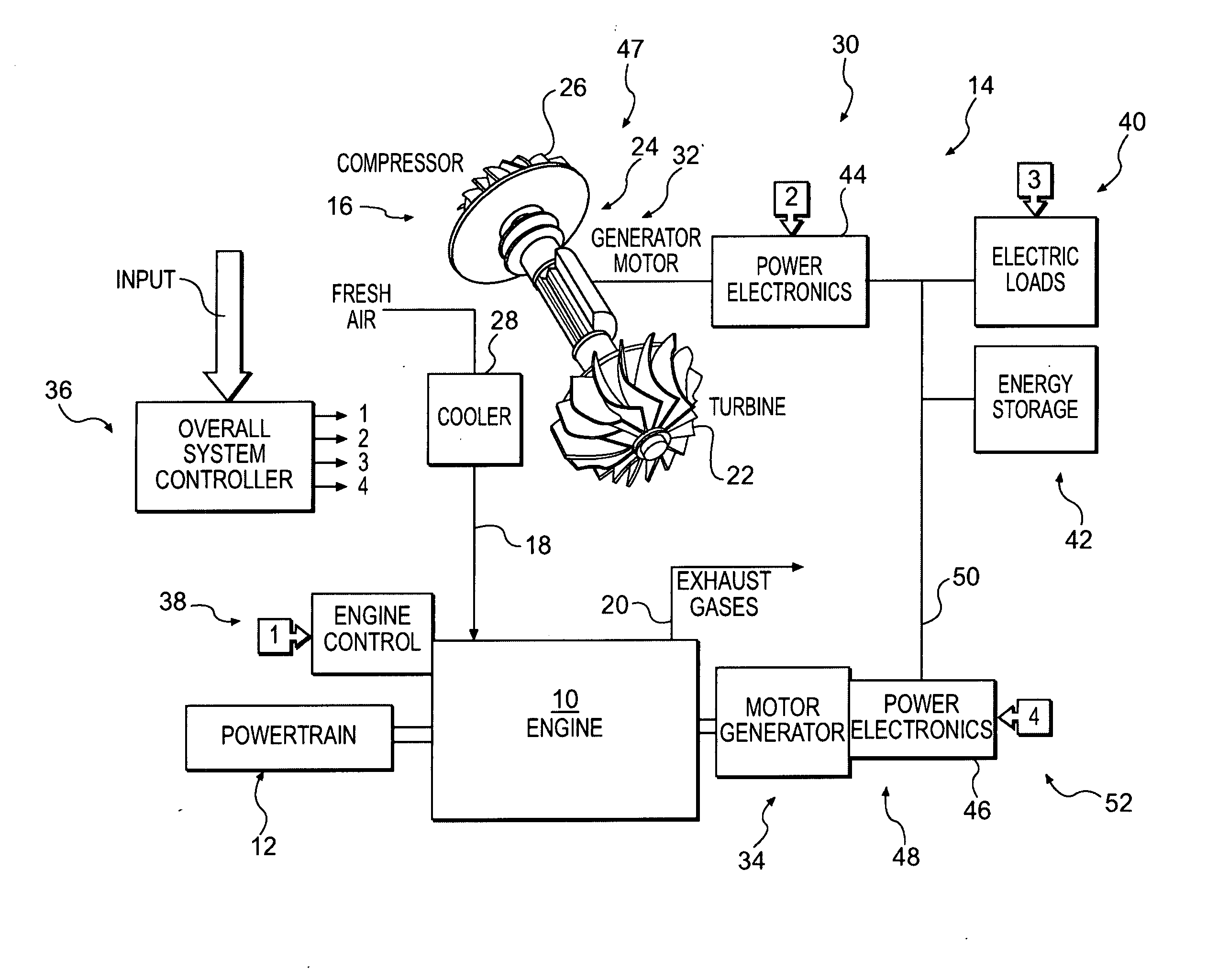
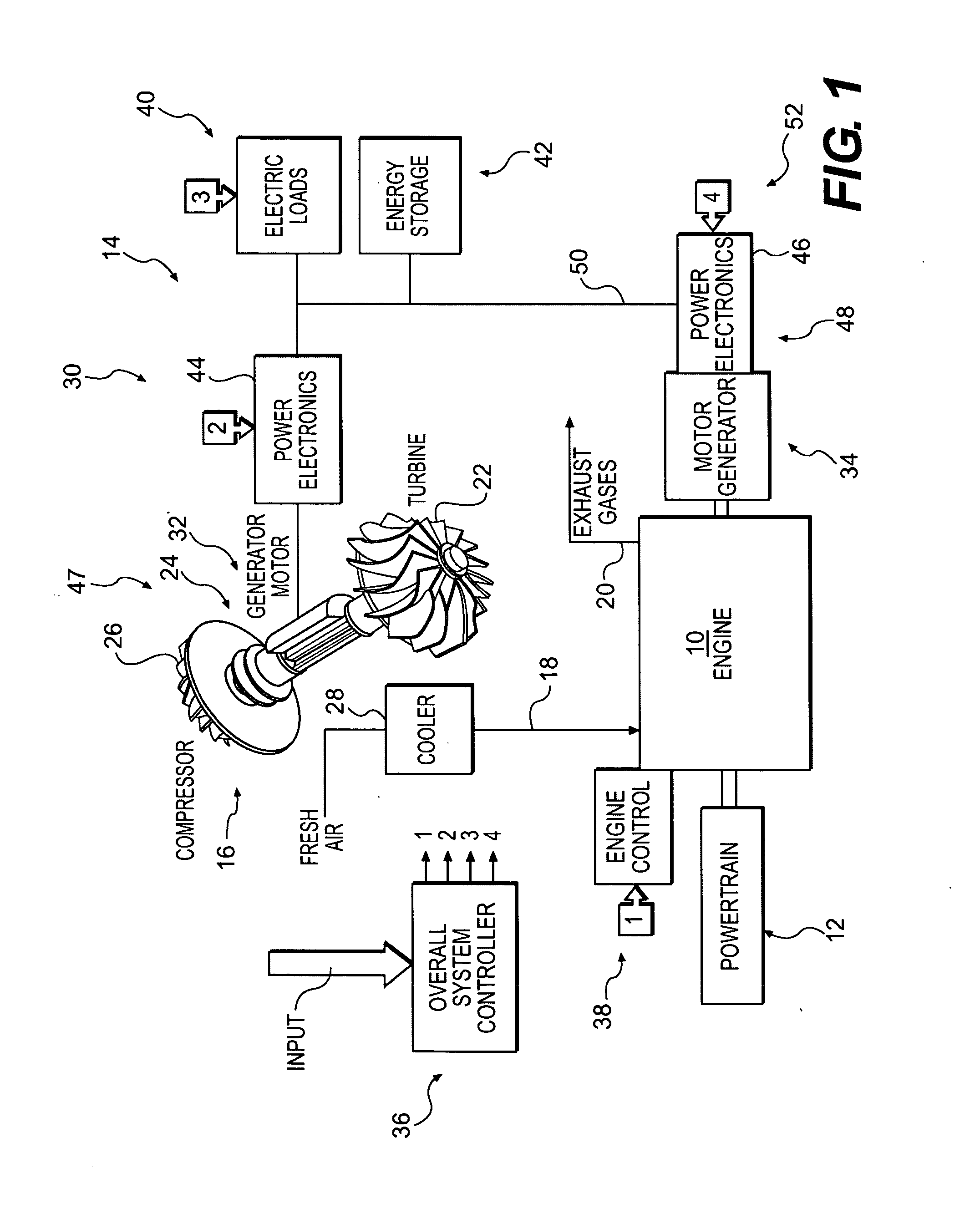
[0040]Referring to FIG. 1, an engine 10 is shown associated with a load or power train 12 which the engine 10 drives during its operation. Commonly, a power train 12 may be a transmission, drive shaft, and wheels of a vehicle or machine (not shown). Alternatively (or additionally), the power train 12 may be in the form of a generator used to produce electrical energy, such as a stationary power generator. Engine 10 may be, for example, a four cycle (i.e., four-stroke) internal combustion engine, and may include multiple cylinders. Engine 10 may be a compression ignited engine, such as a diesel engine, and may be fueled by any fuel generally used in a compression ignited engine, such as diesel fuel. Alternatively, engine 10 may be of the spark ignited type and may be fueled by gasoline, natural gas, methane, propane, or any other fuel generally used in spark ignited engines.

[0041]FIG. 20 diagrammatically illustrates certain operational details in connection with one cylinder of engin...


PUM


Abstract

A turbocompound system for an engine is disclosed. The system includes at least one turbocharger. At least one first electric machine is rotatably coupled to the at least one turbocharger, and a second electric machine is rotatably coupled to the engine. The system further includes a control system configured to enable recovery of energy through operation of the at least one first electric machine and the second electric machine.

Description

[0001]This application is a continuation-in-part of U.S. patent application Ser. No. 11 / 010,958, filed Dec. 13, 2004, the entire contents of which are hereby incorporated by reference.TECHNICAL FIELD[0002]The present disclosure relates to an electric turbocompound system of an engine, and more particularly relates to controlling the electrical power consumed and produced by the electric turbocompound system.BACKGROUND[0003]A turbocompound system of an engine assists the engine by putting mechanical power into the crankshaft of the engine. The mechanical power is developed through an electric machine that acts as a motor and is connected to the crankshaft. The electrical power that drives the motor is produced by another electric machine that is associated with a turbocharger and that acts as a generator. Typically, this generator operates as such by rotation of the turbocharger shaft, and the turbocharger shaft rotates in response to exhaust gases from the engine that turn a turbine...

Claims


Application Information

Patent Timeline
IPC IPC(8): F02B33/00F02B33/44
CPCF02B37/013F02B37/10F02B39/10F02B41/10F02B37/004Y02T10/144Y02T10/142Y02T10/163F02D13/0269Y02T10/12
Inventor ALGRAIN, MARCELO C.
Owner CATERPILLAR INC
Why Eureka
Try Eureka