
RF-enabled pallet

a technology of rf and pallets, applied in the field of plastic pallets, can solve the problems of adding user costs, difficult to keep track of wooden pallets, and problems with wooden pallets

Inactive Publication Date: 2008-05-29
NEXTREME
View PDF99 Cites 49 Cited by
  • Summary
  • Abstract
  • Description
  • Claims
  • Application Information

AI Technical Summary

Benefits of technology

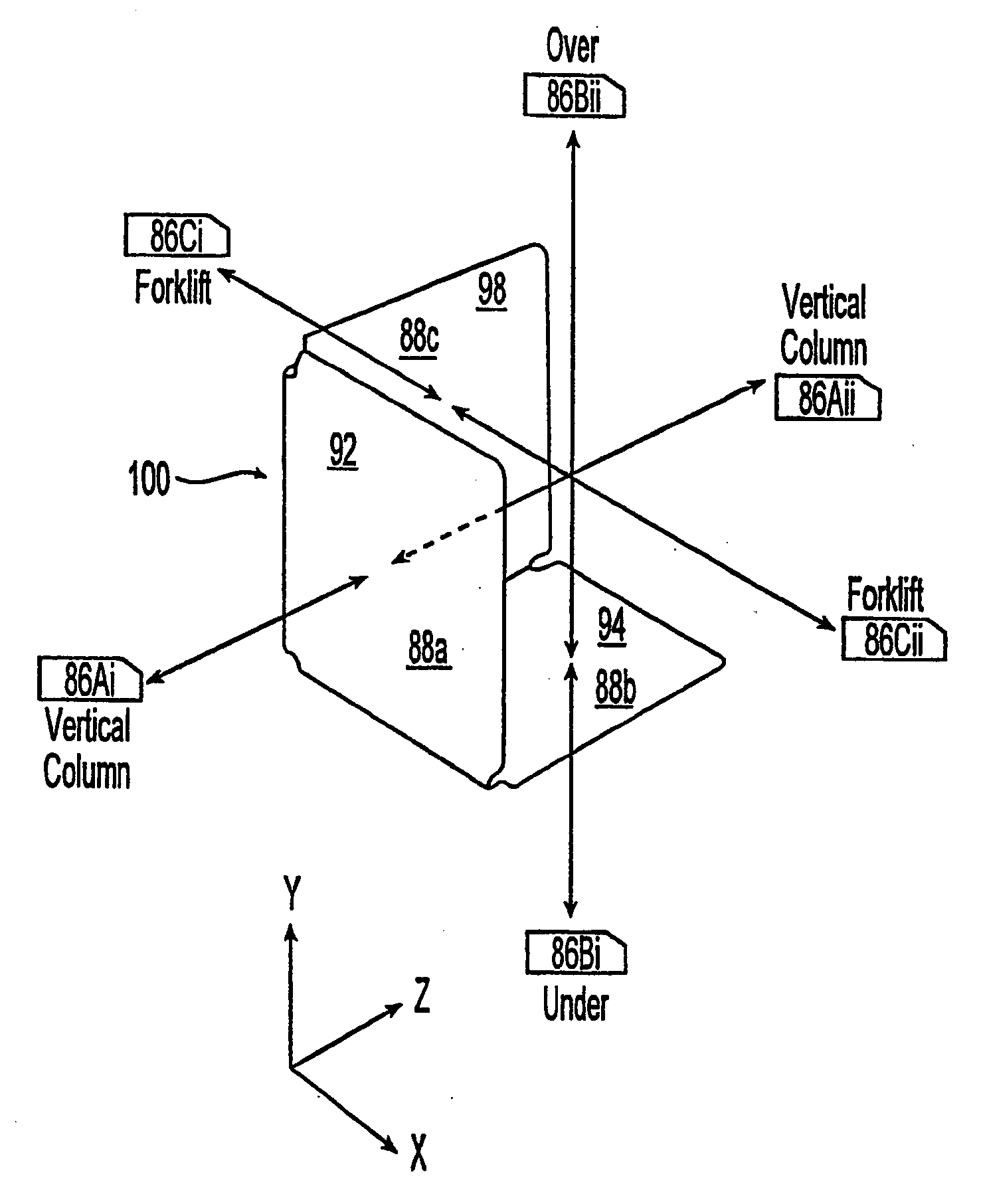
[0024]It is another object to provide a pallet product with multiple unique identification codes so that a plurality of components each with individual IDs can be combined to form a single product having its own unique product ID. This aspect allows a variety of parties to enjoy multiple levels of product identification.

Problems solved by technology

Wooden pallets have problems.
In particular, wooden pallets deteriorate with use and cause problems that add user costs.
Although the business model used by pallet rental companies has enjoyed some success, there have been problems.
For example, it is difficult to keep track of wooden pallets after they are let for hire.
These pallet tracking and other inherent wooden pallet problems have increased the need to modify business models relating to the use of pallets for rental purposes.
Implementation of any RFID system is problematic with regard to wooden pallets.
There are however several problems with such an arrangement.
In the first instance, it is known that wood absorbs liquid and liquids interfere with radio frequency signals.
Therefore, the reliability of communication between the reader and the tag could be compromised by the wooden materials utilized in the construction of the pallet.
In a second instance, a tag that is exteriorly positioned upon a surface of a wooden pallet would be subject to a high level of the wear and tear.
The impact of a fork tine against an exteriorly positioned tag could result in the destruction of the tag and the loss of the data stored in the memory of the tag.
In the final analysis, wood is not a suitable material for constructing pallets that must work within radio frequency rich environments.
The replacement of wood with plastic has had some success but there have been problems associated with the use of plastic pallets that are to be used in association with track and trace technologies including RFID.
In this arrangement a plurality of tags are required which would be more costly than an arrangement in which only one tag is required.
Although the Favaron et al. arrangement utilizes fewer tags. than the Kralj et al. arrangement, Favaron et al. nevertheless utilizes more than one tag which is less economical than the use of one
ated. Liquids and debris within the socket could damage the tag or result in unreliable communication between the tag and the r
Although the arrangements encasing the RFID tags within the plastic pallet embodiments cited above offer levels of protection superior to the method of application '745, such arrangements nevertheless have additional problems.
In particular, in order to remove, replace or repair the tags of the prior art references, the plastic pallets themselves would have to be deconstructed or destroyed to provide access to the tags.
Accordingly, the prior art does not contemplate an efficient means to either replace defective or damaged tags or to upgrade long lasting plastic pallets with new tags incorporating enhanced capabilities as these become available.
However, in both cases the module could become detached from the associated pallet resulting in the loss of data and possibly the pallet.
This adds complexity to the implementation of RFID methods and systems.
When only a single tag is attached to one side of a pallet, the pallet itself could become an obstacle.
Rotating the pallet is time consuming.
One problem with U.S. patent application Ser. No. 10 / 962,574 is that the through hole could collect debris that could impair the operability of the tag.
As discussed above, the life cycle of a plastic pallet may exceed the useful life cycle of a tag technology.
Although the arrangement does not contemplate the destruction of the plastic pallet to access the tag IC, the recess of U.S. Pat. No. 6,844,857 is not developed to accommodate more than one tag IC at a time.
This is a problem because there is a need to provide pallets with a plurality of tags so that the pallet can function across non-interoperable RFID systems existing within the supply chain.
Such an arrangement is impractical because the first tag incorporated into the plastic pallet that contains the unique pallet ID becomes redundant once the unique ID of the first tag is associated with the unique ID of the second tag.

Method used


Image

  • RF-enabled pallet
  • RF-enabled pallet
  • RF-enabled pallet

Examples


Embodiment Construction

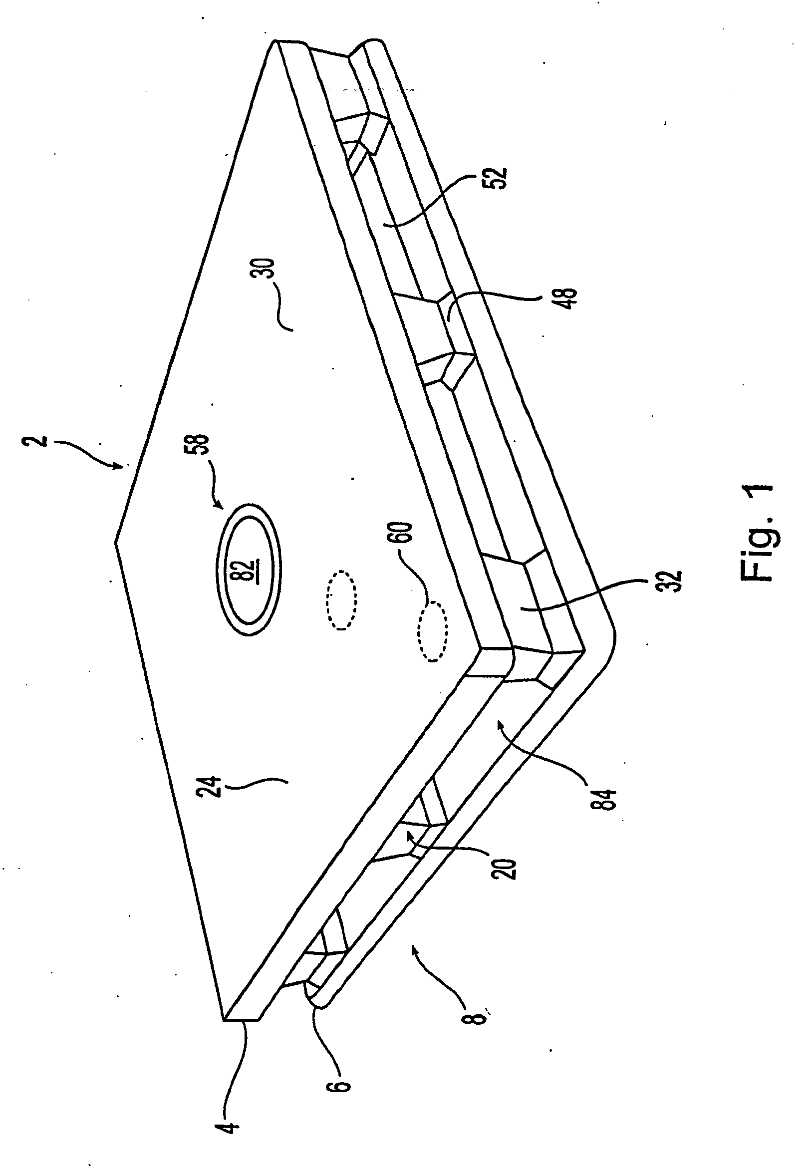
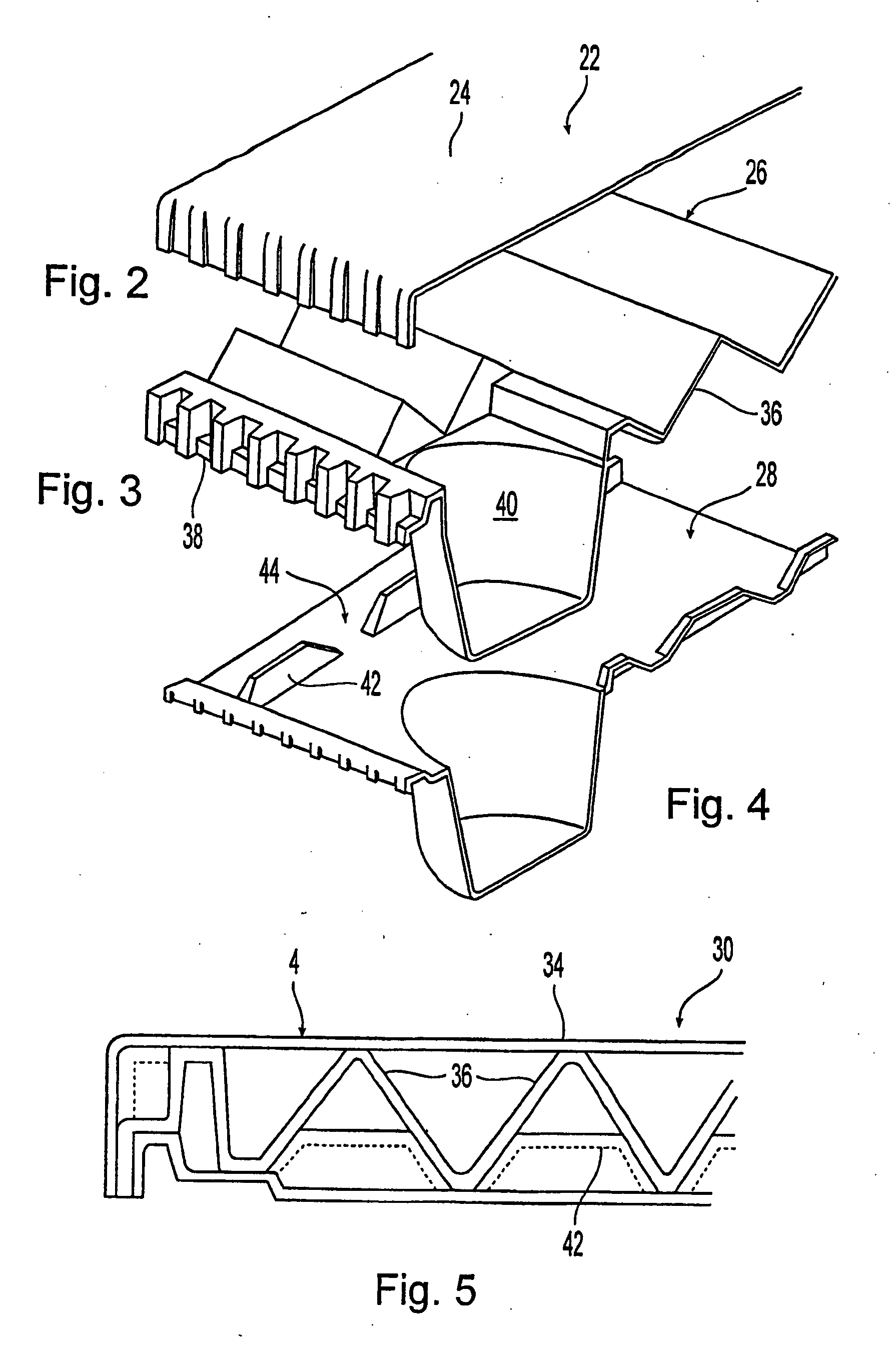
[0042]The present embodiments of pallet structures are merely representative of the principles of the invention and are not intended to limit the scope of the invention or application and uses of the invention. Furthermore, there is no intention to be bound by any expressed or implied theory presented in the preceding technical filed, background, or brief summary of the following detailed description. For example, the pallet structures can be made of any plastic, wood, metal, cellulose material or combination thereof. The pallet structures may be injection molded, blow molded, compression molded, differential pressure formed, stamped, die-cut, fabricated and assembled, welded, and bonded together. The pallets can take the form of GMA style 48×40 inch pallets, nine-legged nestable pallets, shipping trays, returnable dunnage and the like. Other products falling within the scope of the invention include IBCs, RPCs, ULDs, fuel tanks and the like.

[0043]One preferred embodiment involves e...


PUM

PropertyMeasurementUnit
sizesaaaaaaaaaa
timeaaaaaaaaaa
heightaaaaaaaaaa

Abstract

The inventions involve material handling apparatus developed to operate in radio frequency rich environments. Articles are provided having at least one large compartment capable of enclosing at least one electronic device or a package populated with a plurality of devices. RFID tags are also provided having three antenna arrays situated on three planes to improve electromagnetic and electrostatic coupling with an external distributed network of devices. Pallets are provided with cellular communications devices to provide track and trace functionality. Sensors and actuators are used in connection with the material handling apparatus.

Description

CROSS-REFERENCE TO RELATED APPLICATIONS[0001]This application is a continuation of U.S. patent application Ser. No. 11 / 152,628 filed on Jun. 14, 2005, which claims the benefit of U.S. patent application Ser. No. 09 / 770,097 filed on Jan. 24, 2001, which claims the benefit of U.S. Provisional Application No. 60 / 177,382, filed Jan. 24, 2000. This application further claims the benefit of U.S. patent application Ser. No. 10 / 134,049 filed Apr. 26, 2002, which claims the benefit of U.S. Provisional Application No. 60 / 286,450 filed on Apr. 27, 2001, now U.S. Pat. No. 6,661,339, which issued Dec. 9, 2003. This application further claims the benefit of U.S. patent application Ser. No. 10 / 798,932 filed Mar. 11, 2004, which is a continuation of U.S. patent application Ser. No. 09 / 803,681 filed on Mar. 12, 2001, which claims the benefit of U.S. Provisional Application 60 / 196,127 filed on Apr. 11, 2000, now U.S. Pat. No. 6,718,888. The disclosures of the above applications are incorporated herei...

Claims


Application Information

Patent Timeline
Patent Type & Authority Applications(United States)
IPC IPC(8): G08B26/00G08B13/14H04W4/02
CPCB65D19/0016Y10T29/49826B65D2203/10B65D2519/00034B65D2519/00069B65D2519/00139B65D2519/00273B65D2519/00293B65D2519/00303B65D2519/00323B65D2519/00333B65D2519/00358B65D2519/00437B65D2519/00442B65D2519/00562B65D2519/00567G06K19/07758G06K19/07792G08B13/2474H01Q1/2225H01Q21/24H01Q21/28G06Q10/0631G06Q50/28H04W4/02H04W88/06B65D19/38Y02W30/80G06Q10/08
Inventor MUIRHEAD, SCOTT A.W.
Owner NEXTREME
Learn More