Range image system for obtaining subject image of predetermined distance position

a range image and distance position technology, applied in the field of range image system, can solve the problems of inability to correctly obtain range information, the remarkably deteriorating/n ratio of range image, etc., and achieve the effect of improving the size and the cost simplifying the structure of the range image system

Inactive Publication Date: 2008-05-29
FUJIFILM CORP
View PDF3 Cites 56 Cited by
  • Summary
  • Abstract
  • Description
  • Claims
  • Application Information

AI Technical Summary

Benefits of technology

[0009]The range image system of the present invention performs imaging of the visible light and the infrared light every one-frame scanning period and performs the emission of the infrared pulsed light every other one-frame scanning period. The range image system produces the visible-light image every one-frame scanning period. In addition, the infrared pixel signal obtained by imaging of the non-emission time of the pulsed light is subtracted from the infrared pixel signal obtained by imaging of the emission time of the pulsed light to produce the range image. Thus, while the visible-light image is produced, it ...

Problems solved by technology

Consequently, there arises a problem in that an S/N ratio of the range image remarkabl...

Method used


Image

  • Range image system for obtaining subject image of predetermined distance position
  • Range image system for obtaining subject image of predetermined distance position
  • Range image system for obtaining subject image of predetermined distance position

Examples


Embodiment Construction

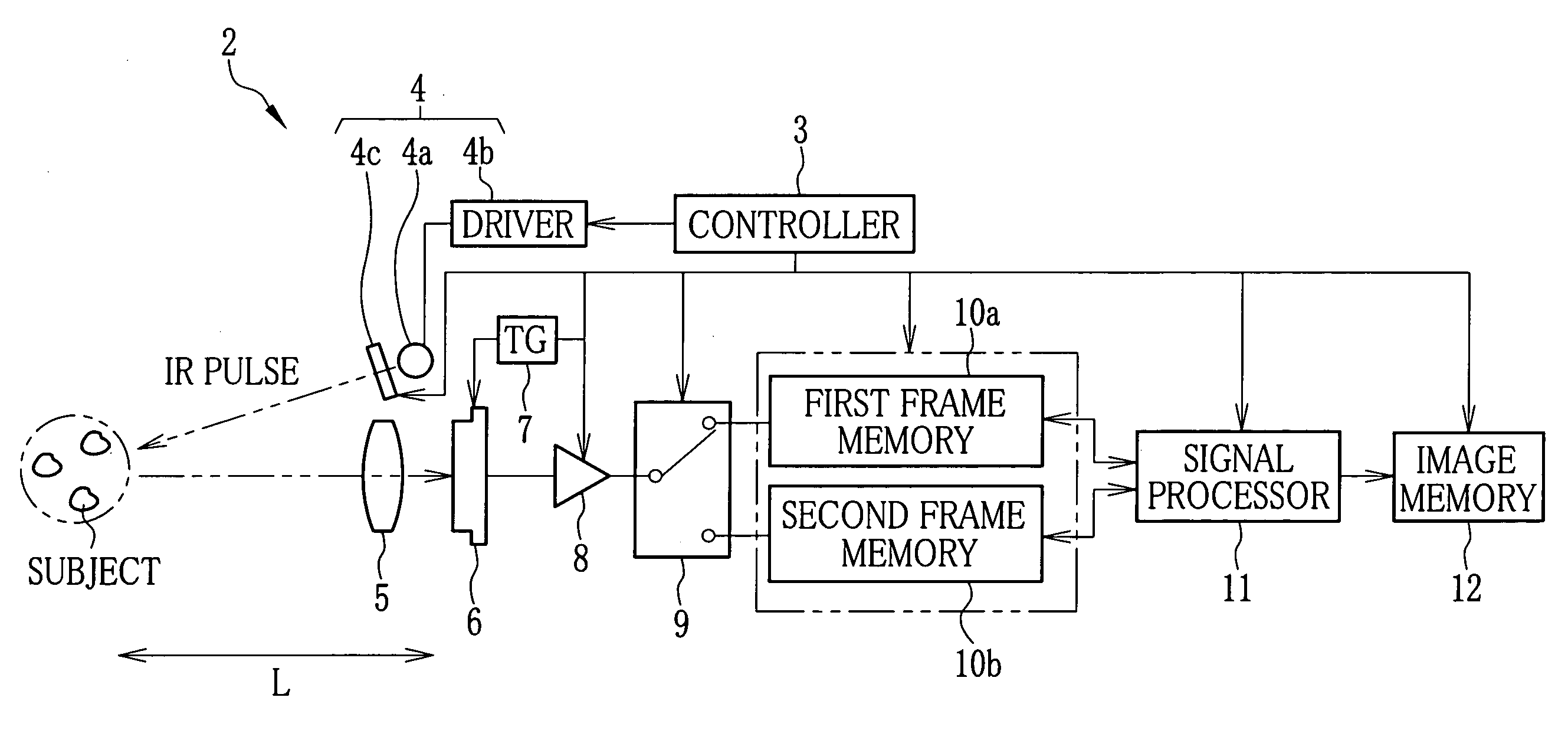
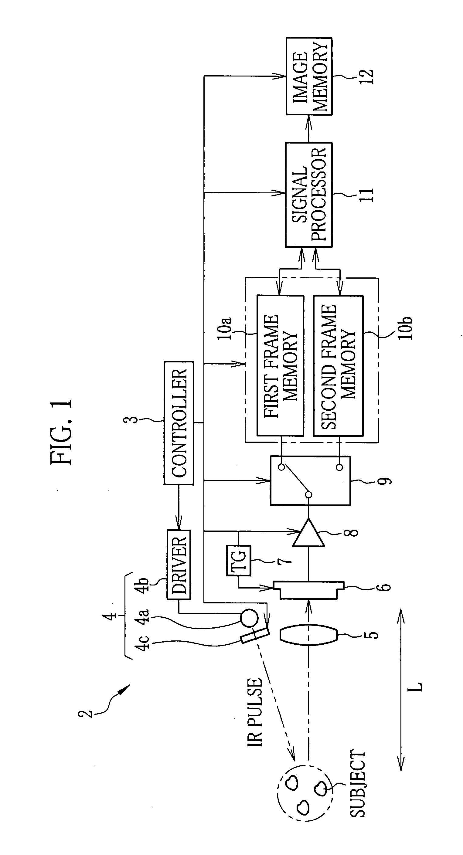
[0019]In FIG. 1, a range image system 2 according to the present invention comprises a controller 3, an IR emitting device 4, a lens 5, a solid-state imaging device 6, a timing generator (TG) 7, an A / D converter 8, a recording-destination changer 9, first and second frame memories 10a and 10b, a signal processor 11 and an image memory 12. The controller 3 integrally controls the respective sections of the range image system 2. The IR emitting device 4 emits infrared (IR) light toward a space to be shot. The lens 5 condenses the visible light and the IR light from the space to be shot. The solid-state imaging device 6 photoelectrically converts the light condensed by the lens 5 to output pixel signals. The timing generator 7 generates various kinds of drive pulses for activating the solid-state imaging device 6. The A / D converter 8 digitizes the pixel signal outputted from the imaging device 6. The recording-destination changer 9 changes a recording destination of the digitized pixel...


PUM


Abstract

A solid-state imaging device has a single plate structure and is capable of imaging of visible light and infrared light. While imaging of the visible light and the infrared light is performed by the imaging device every one-frame scanning period, an IR pulse is emitted, every other one-frame scanning period, to a space to be shot. A visible-light image is produced every one-frame scanning period. A range image from which influence to be caused by infrared component of the ambient light is removed is produced every other one-frame scanning period by subtracting an IR pixel image (S2IR), which is obtained by imaging of non-emission time of the IR pulse, from an IR pixel signal (S1IR), which is obtained by imaging of emission time of the IR pulse.

Description

FIELD OF THE INVENTION[0001]The present invention relates to a range image system for obtaining a subject image (range image) residing at a position of a predetermined distance, and particularly relates to a range image system for obtaining both of a range image and a normal image (visible-light image).BACKGROUND OF THE INVENTION[0002]In recent years, a range image system utilizing an optical-path-difference detection method is known (see U.S. Pat. No. 6,057,909, for instance). In this detection method, infrared pulsed light is emitted to a space to be shot, and the pulsed light reflected by a subject is taken after a predetermined period to obtain a subject image (range image) residing at a position of a predetermined distance (optical path difference). The range image system described in the above-noted US patent employs a solid-state imaging device for receiving the infrared light. Further, a high-speed shutter device of an electrooptical shutter, an image intensifier and so fort...

Claims


Application Information

Patent Timeline
IPC IPC(8): H04N5/33G01C3/06G01S17/10G01S17/89H01L27/148H04N5/225H04N5/335H04N5/357H04N9/07
CPCH01L27/14621H01L27/14627H01L27/14837H04N2209/045H04N5/33H04N5/332H04N9/045H01L27/14887H04N23/11
Inventor MURAYAMA, JIN
Owner FUJIFILM CORP
Why Eureka
Try Eureka