Raman amplifier

a technology of amplifier and amplifier, applied in the field oframan amplifier, can solve the problems of affecting so as to improve the accuracy of estimation of ass light generation amount and satisfy the gain characteristic

Inactive Publication Date: 2008-05-29
FUJITSU LTD
View PDF13 Cites 15 Cited by
  • Summary
  • Abstract
  • Description
  • Claims
  • Application Information

AI Technical Summary

Benefits of technology

[0031]An object of the present invention is to provide a Raman amplifier that can obtain a satisfactory gain characteristic even if the amplifier is used in an optical transmission system in which the optical characteristic of a transmission line is different, by improving the accuracy of estimation of the ASS light generation amount.

Problems solved by technology

(1) Since a Raman amplifier uses an optical fiber, which is a transmission line, as an amplification medium, individual differences occur in the optical characteristics of transmission line fibers due to a) local optical loss which occurs at a site where the Raman amplifier is placed, such as loss in the connecting portion of an optical fiber connected to the Raman amplifier, bending loss, etc.
As a result, with the conventional method for estimating the ASS light generation amount from the intensity of pump light, the accuracy of estimation deteriorates, leading to difficulties in the accurate calculation of the intensity of signal light from which the ASS light generation amount is subtracted.
When this detection capability detects that the signal light does not reach, it transmits a message that communications are abnormal, and shuts down the system.
However, since ASS light mixes along with the signal light as a result of the Raman amplification, the accuracy of detecting the presence / absence of signal light becomes problematic in some cases.
In particular, in a WDM transmission using a broad wavelength range, the number of mixed noise components becomes large.
This poses a problem from the viewpoint of security of an optical communication system.
However, the following problems still remain in the above described methods (1) and (2).
With the above described method (1), the length of time taken to make the measurement beforehand in the design phase of the Raman amplifier and the amount of information stored in the Raman amplifier increase as the individual differences in the optical characteristics of an optical fiber connected to the Raman amplifier become large, leading to inefficiencies.
Furthermore, an error in the estimation of the ASS light generation amount caused by a mismatch between optical characteristics occurs if the optical characteristic of the connected optical fiber and that of an optical fiber that is measured beforehand or stored do not match and information about an optical fiber having a similar optical characteristic is used.
Therefore, procedures for preparing system operations become complicated.
Furthermore, if the intensity of pump light at the time of system operations and that of pump light that is measured when the Raman amplifier is set up do not match (if the ratios of the intensities of pump lights do not match when the wavelengths of the plurality of pump lights are used), then the accuracy of estimation of the ASS light generation amount deteriorates.
Therefore, estimation of the ASS light generation amount at a high level of accuracy cannot be guaranteed.
This leads to a problem in which the accuracy of estimation deteriorates because a calculation formula for accurately estimating the ASS light generation amount cannot be corrected to cope with a change in the ASS light generation amount that occurs with a change in the optical characteristic of the optical fiber.
As a result, the intensity of the signal light cannot be accurately grasped.
Therefore, suitable corrections are not made to changes in the optical characteristic of a transmission line fiber that occur during operations.

Method used


Image

  • Raman amplifier
  • Raman amplifier
  • Raman amplifier

Examples


Embodiment Construction

[0054]The best mode for carrying out the present invention is described in detail below with reference to the drawings.

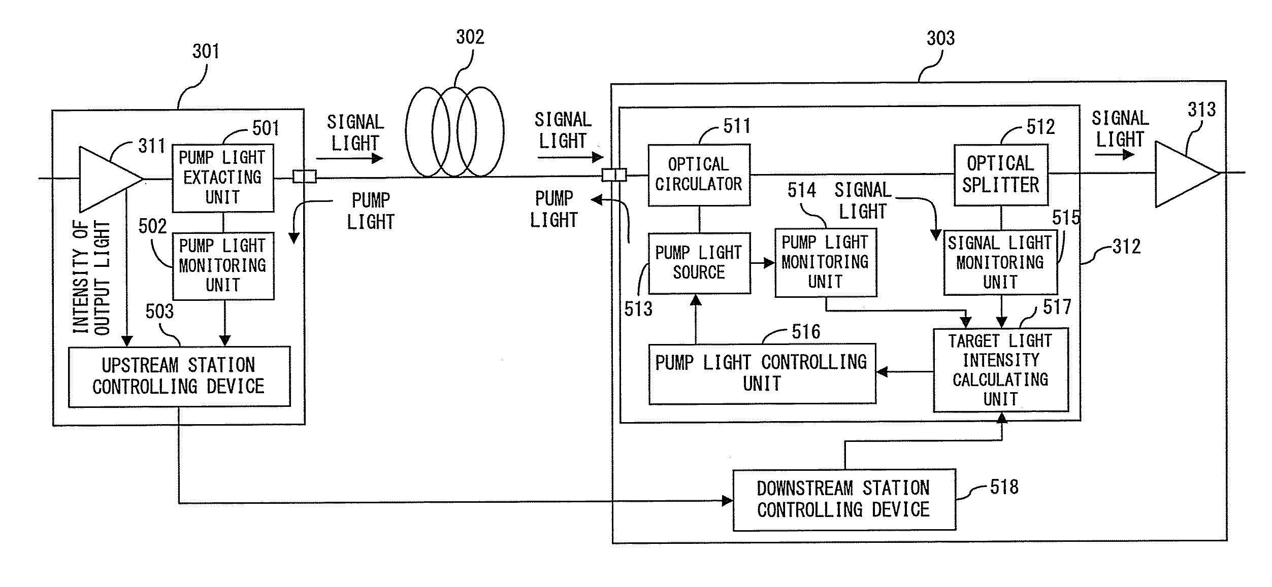
[0055]In the preferred embodiment, transmission line information such as the loss value of a transmission line fiber including losses within a receiving end station, the transmission line information representing the optical characteristic of the transmission line fiber, is monitored continuously on the basis of a light intensity difference between a residual pump light intensity monitored by a light receiving element placed in an upstream transmitting end station and the intensity of pump light made incident, from a Raman amplifier placed in a downstream receiving end station, to the transmission line fiber.

[0056]Additionally, a Raman gain is monitored continuously on the basis of the loss of a transmission line, which is obtained from the above described light intensity difference, the intensity of signal light output from the transmitting end station, and the int...


PUM

PropertyMeasurementUnit
wavelengthaaaaaaaaaa
optical lossaaaaaaaaaa
residual intensityaaaaaaaaaa

Abstract

When pump light is supplied to a transmission line fiber from a downstream station toward an upstream station and signal light from the upstream station is Raman-amplified, a corresponding intensity of amplified spontaneous scattering light is calculated from a required Raman gain by using a correlation between a Raman gain and the intensity of amplified spontaneous scattering light that occurs with Raman amplification, and further a target light intensity is calculated from the obtained intensity of the amplified spontaneous scattering light and the intensity of the amplified signal light. Then, the intensity of the pump light is controlled so that the intensity of light, which is measured by the downstream station, becomes equivalent to the target light intensity.

Description

CROSS REFERENCE TO RELATED APPLICATION[0001]This application is a continuation application of International PCT Application No. PCT / JP2005 / 011298 which was filed on Jun. 20, 2005.BACKGROUND OF THE INVENTION [0002]1. Field of the Invention[0003]The present invention relates to a Raman amplifier for amplifying signal light for an optical communication, an optical communication system comprising the Raman amplifier, and a controlling device of the Raman amplifier.[0004]2. Description of the Related Art[0005]Raman amplifiers are being put into practical use as a technique for building a network for a long-distance transmission optical communication system that can perform large-capacity communications. The Raman amplifier uses an optical fiber as an amplification medium by making pump light having a high intensity be incident to a transmission line fiber.[0006]The Raman amplifier uses the physical phenomenon whereby a Raman amplification effect occurs in the wavelength range that depend...

Claims


Application Information

Patent Timeline
Patent Type & Authority Applications(United States)
IPC IPC(8): H01S3/00G02F1/35H04B10/079H04B10/29H04B10/294
CPCH01S3/06754H04B10/2916H01S3/302H01S3/1305
Inventor NAKATA, MASAO
Owner FUJITSU LTD
Why Eureka
Try Eureka