Image fixing device and image formation apparatus using the same

a technology of fixing device and fixing member, which is applied in the direction of electrographic process apparatus, instruments, optics, etc., can solve the problems of short heating time of fixing member and accuracy of detecting temperature, and achieve the effect of preventing inrush current, simple structure and small electric power source capacity

Inactive Publication Date: 2008-05-29
RICOH KK
View PDF2 Cites 18 Cited by
  • Summary
  • Abstract
  • Description
  • Claims
  • Application Information

AI Technical Summary

Benefits of technology

[0007]The invention presented in this application prevents the inrush current from occurring with a simple structure. Further, the invention allows the electric power source capacity to be smaller as the power source does not need to supply the inrush current.
[0008]According to an aspect of the invention, an image fixing device for use in an image forming apparatus includes a fixing member which fixes a toner image on a recording medium at a nip area, a pressurizing member which pressures the recording medium toward the fixing member at the nip area, a carbon lamp which emits infrared rays, and a reflecting member which reflects the infrared rays to the nip area. The carbon lamp and the reflecting member suppress an inrush current at an initial energization, and allow the electric source capacity to be small. Moreover, the carbon lamp and the reflecting member make the time of heating up the fixing member short and effectively melt and press toner at the nip area. The reflecting member reflects the infrared rays to a most upstream portion of the nip area in the conveying direction of the recording medium. This reflecting member heats toner at the beginning of proceeding the nip area and prevents ineffectual loss of heat. Moreover, the thermistor which is a detecting member for detecting temperature of the fixing member and is opposed to the inner side of fixing member prevents the accuracy of detecting temperature from dropping.
[0009]The fixing member includes a plurality of materials which have different heat absorptivities. The plurality of materials allows better absorption of the heat energy corresponding to the wavelength range of the infrared rays emitted by the carbon lamp. Moreover, the fixing member is made with at least a first layer which contacts the recording medium, a second layer which conveys heat to the first layer, and a third layer which includes a surface facing the carbon lamp. The first, second, and third layers have different heat absorptivities, and convey heat from the third layer, whose heat absorptivity is the highest in the layers of the fixing member, to the first layer which is next to the recording medium. The third layer absorbs the far infrared rays corresponding to the infrared rays given off from the carbon lamp whose wavelength range is mainly from 1 to 10 μm.
[0010]The material of the third layer is made with heat resistant resin, and prevents the third layer from a deformation or a chemical change caused by the heat of the carbon lamp. The thickness of the third layer is 0.5 mm or less and makes the heat capacity of the fixing member small. The small heat capacity of the fixing member reduces the heat up time at the nip area of the fixing member.
[0011]The carbon lamp includes the evaporated reflecting member on the surface of the lamp. The evaporated reflecting member does not need an attachment structure of the reflecting member, and downsizes the image fixing device. A small image fixing device has a small heat capacity and the small heat capacity of the small image fixing device also reduces the heat up time at the nip area of the fixing member. According to one embodiment, the image fixing device includes a plurality of carbon lamps arranged in the width direction of the fixing member which give off a limited infrared ray selectively corresponding to the different widths of the recording mediums. The plurality of carbon lamps prevent the excess heating up at both ends of the fixing member in the width direction where the recording medium does not contact but the fixing member directly contacts with the pressurizing member. The heat damage at both ends is decreased and the heating efficiency is increased.

Problems solved by technology

Moreover, the carbon lamp and the reflecting member make the time of heating up the fixing member short and effectively melt and press toner at the nip area.
Moreover, the thermistor which is a detecting member for detecting temperature of the fixing member and is opposed to the inner side of fixing member prevents the accuracy of detecting temperature from dropping.

Method used


Image

  • Image fixing device and image formation apparatus using the same
  • Image fixing device and image formation apparatus using the same
  • Image fixing device and image formation apparatus using the same

Examples


first embodiment

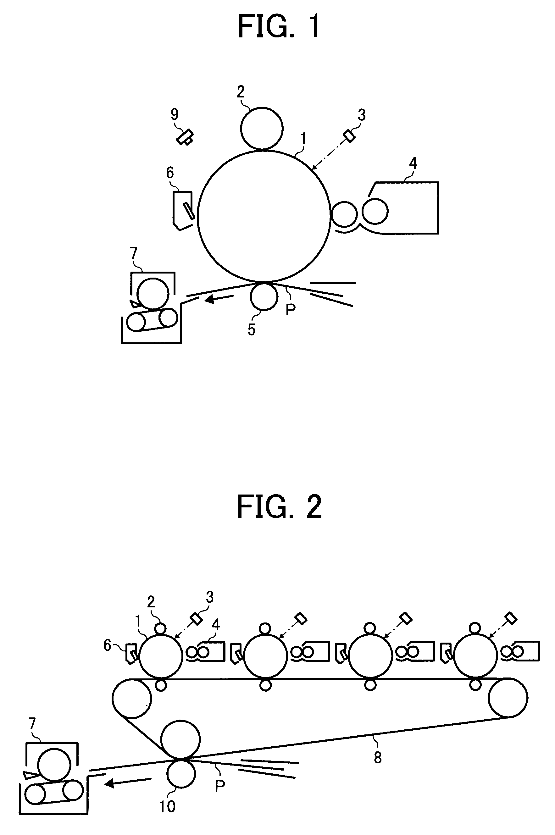
[0030]FIG. 1 is a schematic view of a simple image forming apparatus which includes a fixing device of a This image forming apparatus uses a single color toner and may be considered a simple image forming apparatus. As shown in FIG. 1, the simple color image forming apparatus includes a photoconductive drum 1, a charge roller 2 that charges the surface of the photoconductive drum 1, an exposure device 3 that irradiates an exposure light, which is shown as an arrow based on image information, a developing device 4 that develops a toner image corresponding to the image information on the photoconductive drum, a transferring roller 5 that transfers the toner image on the photoconductive drum 1 to a recording medium P, a cleaning device 6 that removes a residual toner on the photoconductive drum 1, and a quenching lamp 9 that quenches a residual electric potential on the surface of the photoconductive drum 1. With reference to FIG. 1, image forming operations of the image forming appar...

embodiment 1

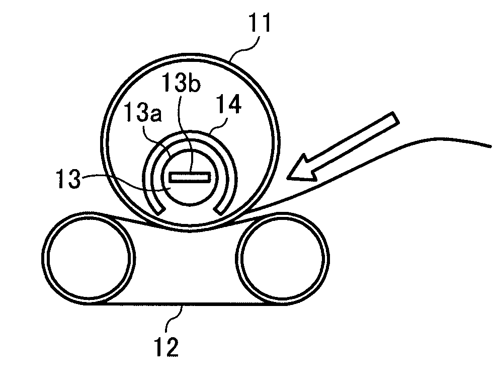
[0038]The improved embodiment based on the embodiment 1 is shown in FIG. 6. FIG. 6 is a schematic view of a fixing device 7 with a thermistor 15. The thermistor 15 is arranged inside the fixing roller 11 in contact with the inner surface of the fixing roller 11. If the thermistor 15 is in contact with the outer surface of the roller 11, which is at the side of contacting with the recording medium P, the thermistor 15 will make the fixing performance become worse. If desired, the thermistor does not need to contact the inner or outer surface of the roller 11. The thermistor 15 detects a temperature of the fixing roller 11 so that the temperature of the roller 11 can be controlled to be within a certain range. It is further preferable that the fixing roller 11 is made with a material which has high heat conductivity like copper, although this is not required. It is because of a temperature difference between a part surface which contacts the recording medium P and other part surface w...

third embodiment

[0039]the present invention will now be described. FIG. 7 is a graph of a relationship between a wavelength distribution of the light given off by the carbon lamp and two wavelength distributions of heat absorptivity of two different materials A and B. The upper graph shows the wavelength distribution of the light given off by the carbon lamp. The lower graph shows the two wavelength distributions of heat absorptivity of the two different materials, A and B. As described in the explanation of FIG. 4, the carbon lamp 13 gives off infrared rays effectively and the peak wavelength of the light of the carbon lamp 13 exists in a range from 1.5 to 8 μm, and is especially centered in a range from 2 to 5 μm.

[0040]On the condition that the upper graph's wavelength distribution of the light which is given off by the carbon lamp corresponds to the far infrared ray's range from 2.5 to 8 μm, either lower graph's wavelength distribution of heat absorptivity which is the fixing member's material A...


PUM


Abstract

An image fixing device for use in an image forming apparatus. The fixing device includes a fixing member which fixes a toner image on a recording medium at a nip area, a pressurizing member which pressures the recording medium toward the fixing member at the nip area, a carbon lamp which emits infrared rays, and a reflecting member which reflects the infrared rays to the nip area.

Description

CROSS-REFERENCE TO RELATED APPLICATION[0001]This patent specification is based on two Japanese patent applications, No. 2006-183189 filed on Jul. 3, 2006 in the Japan Patent Office and No. 2007-068563 filed on Mar. 16, 2007 in the Japan Patent Office, the entire contents of which are incorporated by reference herein.BACKGROUND OF THE INVENTION[0002]1. Field of the Invention[0003]The present invention relates to an image forming apparatus, such as a copy machine, a printer, a facsimile machine, and a multi-function machine capable of copying, printing, and faxing, and more particularly to an image fixing device which uses a carbon lamp.[0004]2. Description of the Related Art[0005]An image fixing device is disclosed in Laid-open Japanese Patent Application No. 2003-215964 as Patent Reference 1. This image fixing device is improved to suppress an inrush current at an initial energization of a heater used for a fixing device for an image forming apparatus. A thermal fixing device of pap...

Claims


Application Information

Patent Timeline
Patent Type & Authority Applications(United States)
IPC IPC(8): G03G15/20
CPCG03G2215/2009G03G15/2053
Inventor NISHIKAWA, TETSUJINIIHARA, TAKAYUKISUZUKI, KAZUKIBANNAI, KAZUNORIKIKURA, MAKOTOMAEHATA, YASUHIRO
Owner RICOH KK
Why Eureka
Try Eureka