Apparatus and method for determining the relative position and orientation of neurostimulation leads

a technology of neurostimulation and apparatus, applied in the field of neurostimulation systems, can solve the problems of inability to obtain images, inability to accurately determine the relative position and orientation of neurostimulation leads, and inability to meet the needs of patients,

Active Publication Date: 2008-05-29
BOSTON SCI NEUROMODULATION CORP
View PDF9 Cites 79 Cited by
  • Summary
  • Abstract
  • Description
  • Claims
  • Application Information

AI Technical Summary

Benefits of technology

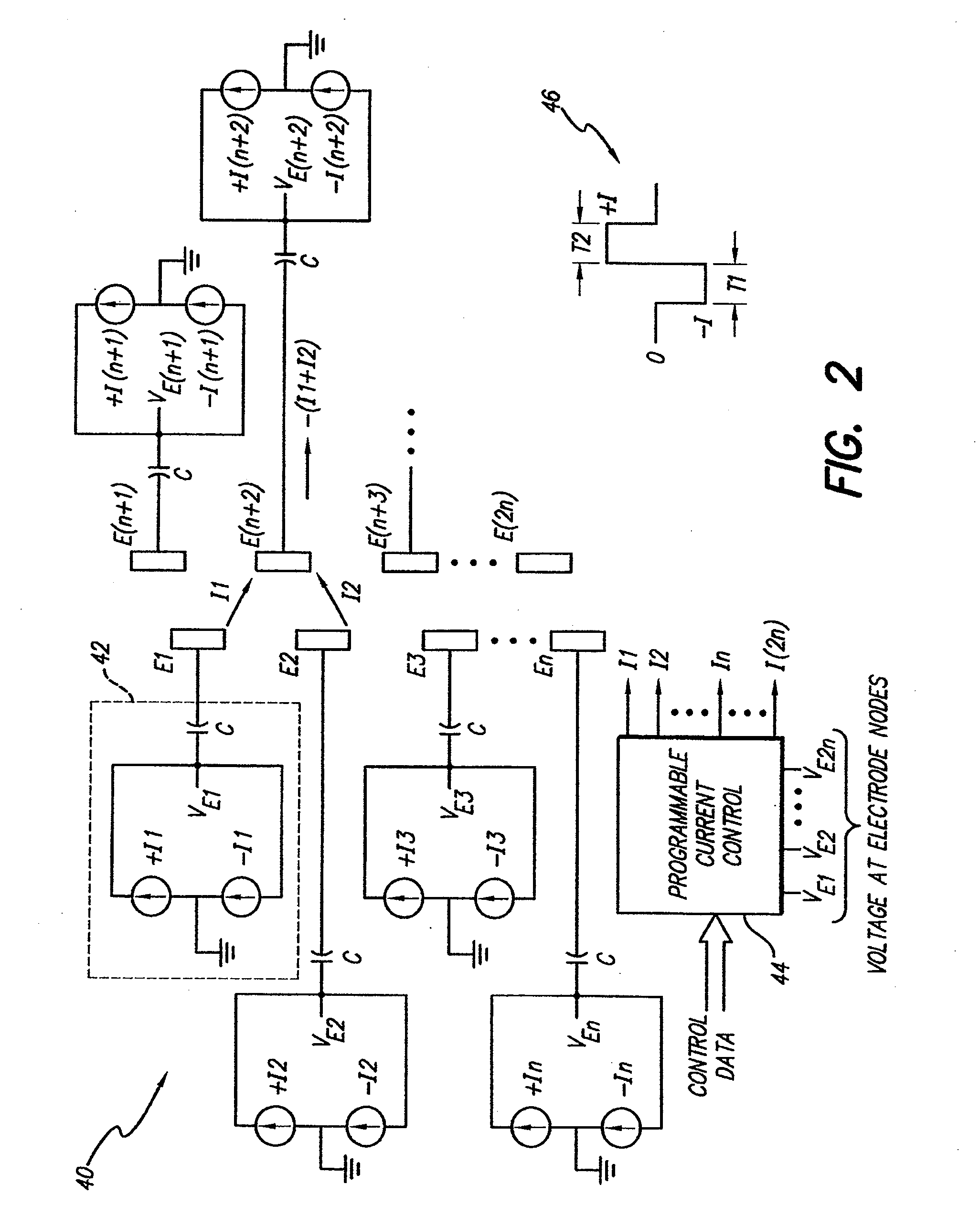
[0007]The present invention addresses the above and other needs by providing a cross-check technique for verifying the position of the electrodes of the implanted leads. A first technique involves the use of interelectrode impedance. A second technique involves measured field potentials. A third technique involves estimated field potentials. Any of these techniques advantageously allows the relative orientation of one electrode on an implanted lead to other electrodes on the implanted lead or adjacent implanted leads in the spinal column or other body / tissue location to be readily determined. Such techniques are useful not only for reprogramming, but also to estimate if the shifted orientation of the electrodes is sufficiently large so as to make electrical reprogramming a waste of time, thereby suggesting that surgery may need to be performed for repositioning.

Problems solved by technology

Disadvantageously, X-ray and fluoroscopy require expensive equipment, significant time, and appropriate medical facilities, most of which are not readily available.
Disadvantageously, however, such images may not always be available.
Moreover, between the time of implant and follow-up visits, the leads may have shifted and the fluoroscope image may no longer be valid.
This can result in poor patient outcomes due to inappropriate or unexpected stimulation effects during fitting.

Method used


Image

  • Apparatus and method for determining the relative position and orientation of neurostimulation leads
  • Apparatus and method for determining the relative position and orientation of neurostimulation leads
  • Apparatus and method for determining the relative position and orientation of neurostimulation leads

Examples


Embodiment Construction

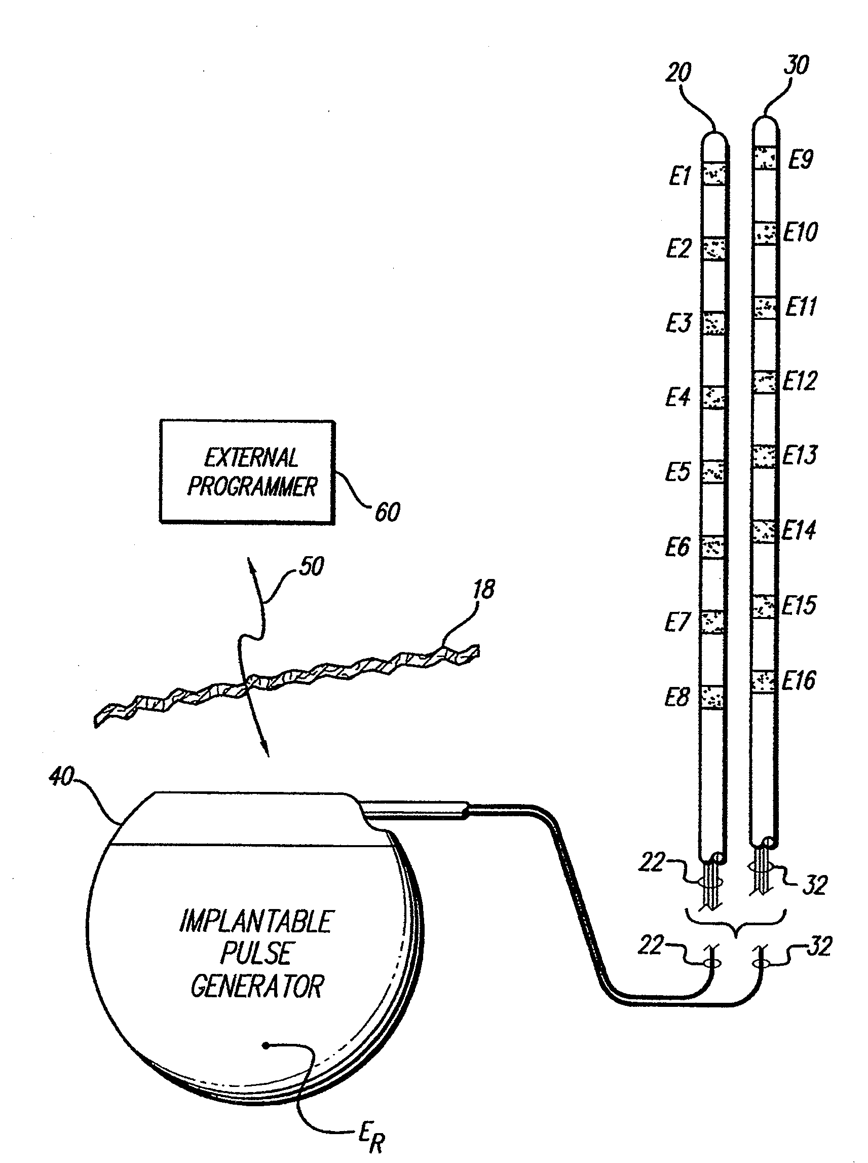
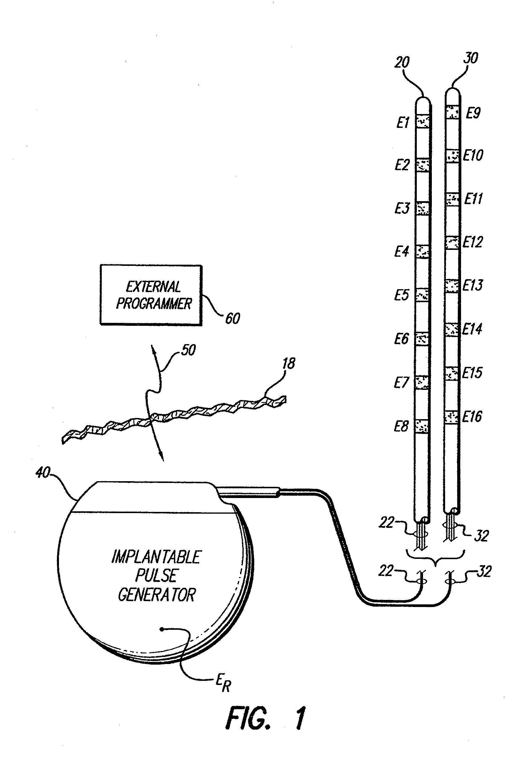
[0027]At the outset, it is noted that the present invention may be used with an implantable pulse generator (IPG), radio frequency (RF) transmitter, or similar electrical stimulator, that may be used as a component of numerous different types of stimulation systems. The description that follows relates to a spinal cord stimulation (SCS) system. However, it is to be understood that while the invention lends itself well to applications in SCS, the invention, in its broadest aspects, may not be so limited. Rather, the invention may be used with any type of implantable electrical circuitry used to stimulate tissue. For example, the present invention may be used as part of a pacemaker, a defibrillator, a cochlear stimulator, a retinal stimulator, a stimulator configured to produce coordinated limb movement, a cortical stimulator, a deep brain stimulator, a peripheral nerve stimulator, or in any other neural stimulator configured to treat urinary incontinence, sleep apnea, shoulder sublax...


PUM


Abstract

A method for determining whether the relative position of electrodes used by a neurostimulation system has changed within a patient comprises determining the amplitude of a field potential at each of at least one of the electrodes, determining if a change in each of the determined electric field amplitudes has occurred, and analyzing the change in each of the determined electric field amplitudes to determine whether a change in the relative position of the electrodes has occurred. Another method comprises measuring a first monopolar impedance between a first electrode and a reference electrode, measuring a second monopolar impedance between second electrode and the reference electrode, measuring a bipolar impedance between the first and second electrodes, and estimating an amplitude of a field potential at the second electrode based on the first and second monopolar impedances and the bipolar impedance.

Description

RELATED APPLICATIONS[0001]The present application is a continuation-in-part of U.S. patent application Ser. No. 11 / 343,007, filed Jan. 30, 2006, which is a continuation of U.S. patent application Ser. No. 10 / 310,202, filed Dec. 3, 2002 (now U.S. Pat. No. 6,993,384), which application claims the benefit of U.S. Provisional Patent Application Ser. No. 60 / 338,331, filed Dec. 4, 2001, each of which is incorporated herein by reference.BACKGROUND OF THE INVENTION[0002]The present invention relates to neurostimulation systems, such as a spinal cord stimulation (SCS) system, and more particularly to a method for determining the relative position and orientation of electrodes on a neurostimulation lead or leads used with such a system.[0003]In SCS systems, positioning of the leads is critical to the success of the therapy. During surgery, the physician places the leads in a very careful manner in order to locate the electrodes proximal to neural elements that are the target of the stimulatio...

Claims


Application Information

Patent Timeline
Patent Type & Authority Applications(United States)
IPC IPC(8): A61N1/08
CPCA61B5/053A61N1/08A61N1/0551A61N1/3605A61N1/37247
Inventor BRADLEY, KERRYTHACKER, JAMES R.MOFFITT, MICHAEL A.
Owner BOSTON SCI NEUROMODULATION CORP
Why Eureka
Try Eureka