
Electronic apparatus

a technology of electronic equipment and main memory, applied in the direction of microcontrollers, instruments, program control, etc., can solve the problems of high cost, system inflexibility, and program cannot be directly executed without being located into a main memory, and achieve the effect of low cos

Inactive Publication Date: 2008-05-29
FUJIFILM CORP
View PDF15 Cites 33 Cited by
  • Summary
  • Abstract
  • Description
  • Claims
  • Application Information

AI Technical Summary

Benefits of technology

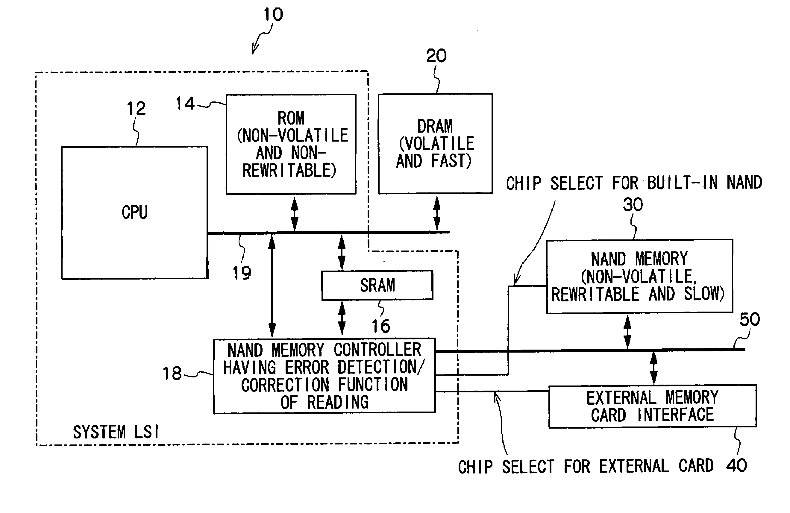
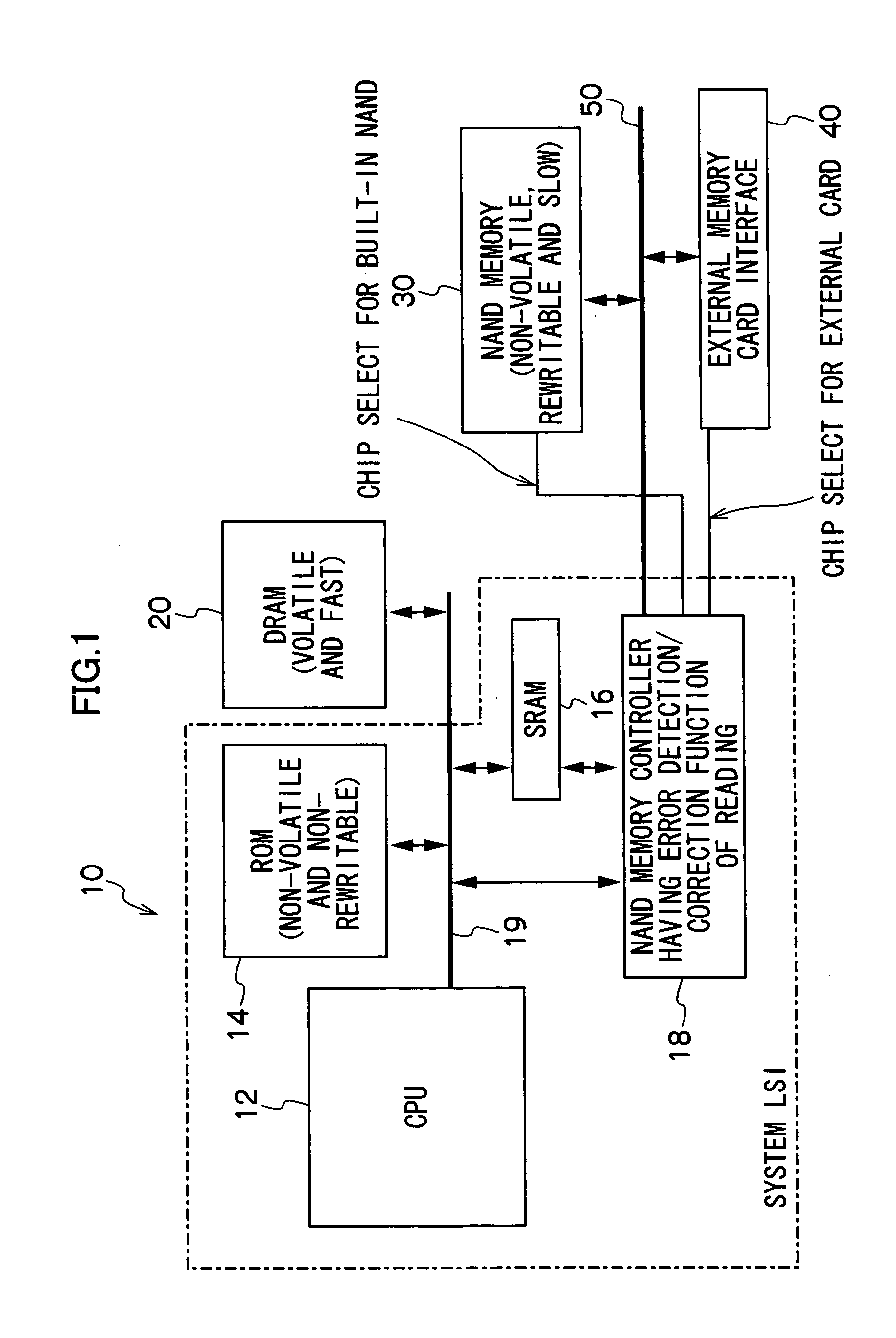
[0014]The present invention has been contrived in view of the foregoing circumstances, and the object is to provide an electronic apparatus which can construct a low-cost and flexible system in the electronic apparatus storing the main program in the serial flash memory.

Problems solved by technology

NAND flash memory, however, has such disadvantages that data stored in NAND flash memory cannot be accessed by a byte at a time unlike NOR flash memory but accessed on a block-wise basis; and hence, when executing a program stored in NAND flash memory, the program cannot be directly executed without being located into a main memory.
The system needs a dedicated sequencer (transferring apparatus) that controls the NAND flash memory without relying on the CPU, and the dedicated sequencer cannot be shared with an interface for an external memory card, so that it becomes high-cost.
This system cannot be flexible because the device for initializing the RAM is fixed.
Any usage of the above-described NAND flash memory controller is limited to the program storage and the access to one NAND flash memory, and it is not shared with an access device to an exchangeable NAND flash memory such as an external memory card.
Hence, when the external memory card is used, as another controller is necessary, it becomes high-cost.

Method used


Image

  • Electronic apparatus
  • Electronic apparatus
  • Electronic apparatus

Examples


first embodiment

[0052]FIG. 3 is a flowchart illustrating operations for starting the electronic apparatus according to a first embodiment of the present invention.

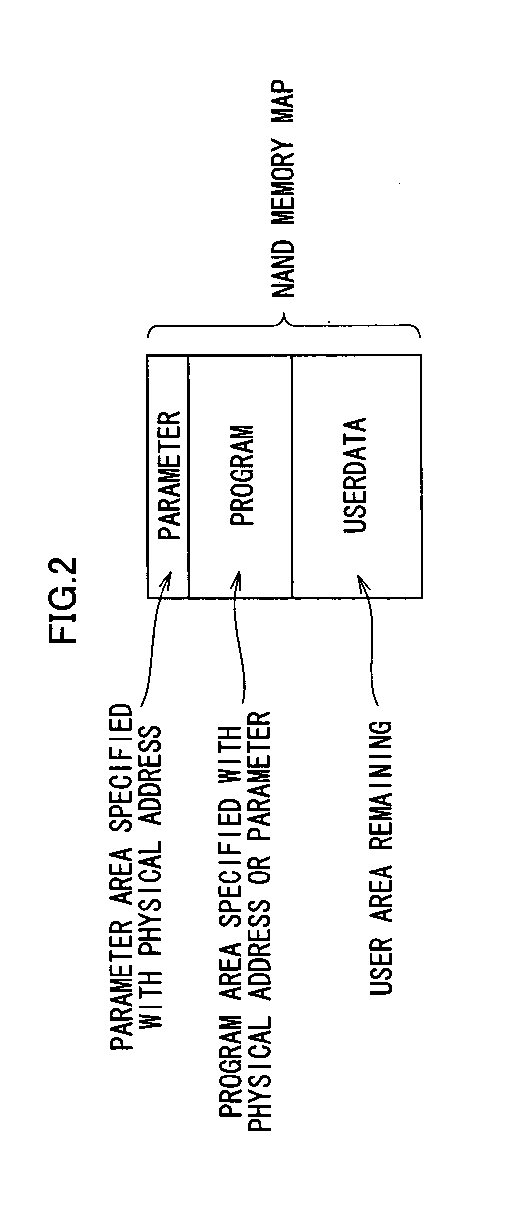
[0053]When the electronic apparatus is powered on (or when the power-on reset is executed), the CPU 12 first executes the ROM code in the ROM 14 to perform the initialization of the system that is minimally necessary to control the NAND memory controller 18, then selects only the chip select signal for the NAND flash memory 30 by controlling the NAND memory controller 18, accesses the area designated with the specific physical address (the first page of the first block) of the NAND flash memory 30, reads parameters from the designated area, and locates the read parameters into the SRAM 16 (step S10).

[0054]The CPU 12 then performs the system initialization by using the parameters stored in the SRAM 16 (step S12). Since the SRAM 16 does not require initialization, the CPU 12 can immediately access the SRAM 16, and can initialize and set the...

second embodiment

[0058]FIG. 4 is a flowchart illustrating operations for starting the electronic apparatus according to a second embodiment of the present invention. The steps described in the first embodiment with reference to FIG. 3 are denoted with the same reference numerals in FIG. 4, and the detailed description thereof is omitted.

[0059]In the second embodiment illustrated in FIG. 4, the processing of step S20 is executed instead of step S12 of the first embodiment.

[0060]The parameters stored in the NAND flash memory 30 include a parameter for initializing the DRAM 20.

[0061]At step S20 for initializing the system, the CPU 12 initializes the DRAM 20 by using the parameter for initializing the DRAM 20, which parameter is one of the parameters stored in the SRAM 16. Thereby, any of DRAMs of various capacities and types can be used.

third embodiment

[0062]FIG. 5 is a flowchart illustrating operations for starting the electronic apparatus according to a third embodiment of the present invention. The steps described in the first embodiment with reference to FIG. 3 are denoted with the same reference numerals in FIG. 5, and the detailed description thereof is omitted.

[0063]In the third embodiment illustrated in FIG. 5, the processing of step S22 is executed instead of step S12 of the first embodiment.

[0064]The parameters stored in the NAND flash memory 30 include a parameter for setting a clock frequency of the system, which is used when the CPU 12 transfers the main program from the NAND flash memory 30 to the DRAM 20, and a parameter for setting a pulse width of a control signal, which is used when the CPU 12 accesses the NAND flash memory 30.

[0065]At step S22 for initializing the system, the CPU 12 performs setting of the clock frequency of the system and setting of the NAND memory controller 18 for the transfer of the program,...


PUM


Abstract

The electronic apparatus includes: a central processing unit; a non-volatile memory which is non-rewritable and stores a boot program; a first volatile memory which enables fast reading and writing of data and does not require initialization; a second volatile memory which enables fast reading and writing of data and requires initialization; and a first flash memory which is serial and stores at least a parameter necessary for the central processing unit to perform initialization of a system in an area designated with a first physical address, and a main program to be executed by the central processing unit in an area designated with one of a second physical address and the parameter. When the electronic apparatus is powered on, the central processing unit executes the boot program stored in the non-volatile memory so that the central processing unit performs transfer of the parameter from the first flash memory to the first volatile memory by reading the parameter from the first flash memory and temporarily storing the read parameter into the first volatile memory, and then performs the initialization of the system according to the parameter stored in the first volatile memory, thereafter performs transfer of the main program stored in the first flash memory to the second volatile memory, and then starts the main program on the second volatile memory.

Description

BACKGROUND OF THE INVENTION[0001]1. Field of the Invention[0002]The present invention relates to an electronic apparatus, more specifically to a technology for performing system boot of the electronic apparatus of which program (firmware) is stored in a serial flash memory.[0003]2. Description of the Related Art[0004]Serial flash memory (e.g., NAND flash memory) has such advantages that it is less expensive and allows greater storage densities than parallel flash memory (e.g., NOR flash memory). NAND flash memory, however, has such disadvantages that data stored in NAND flash memory cannot be accessed by a byte at a time unlike NOR flash memory but accessed on a block-wise basis; and hence, when executing a program stored in NAND flash memory, the program cannot be directly executed without being located into a main memory.[0005]Moreover, NAND flash memory is permitted to include defective blocks, so that when NAND flash memory is accessed, data are written and read as managing loca...

Claims


Application Information

Patent Timeline
Patent Type & Authority Applications(United States)
IPC IPC(8): G06F15/177
CPCG06F9/4401
Inventor TAKAYAMA, KATSUMI
Owner FUJIFILM CORP
Learn More